
Propeller protector slipper

a technology for protecting slippers and propeller blades, applied in the field of propeller protectors, can solve the problems of affecting the safety of passengers, etc., and achieving the effects of preventing slippage, preventing slippage, and preventing slippag

Inactive Publication Date: 2003-08-26
PITHER ALLAN WALTER
View PDF21 Cites 9 Cited by
  • Summary
  • Abstract
  • Description
  • Claims
  • Application Information

AI Technical Summary

Benefits of technology

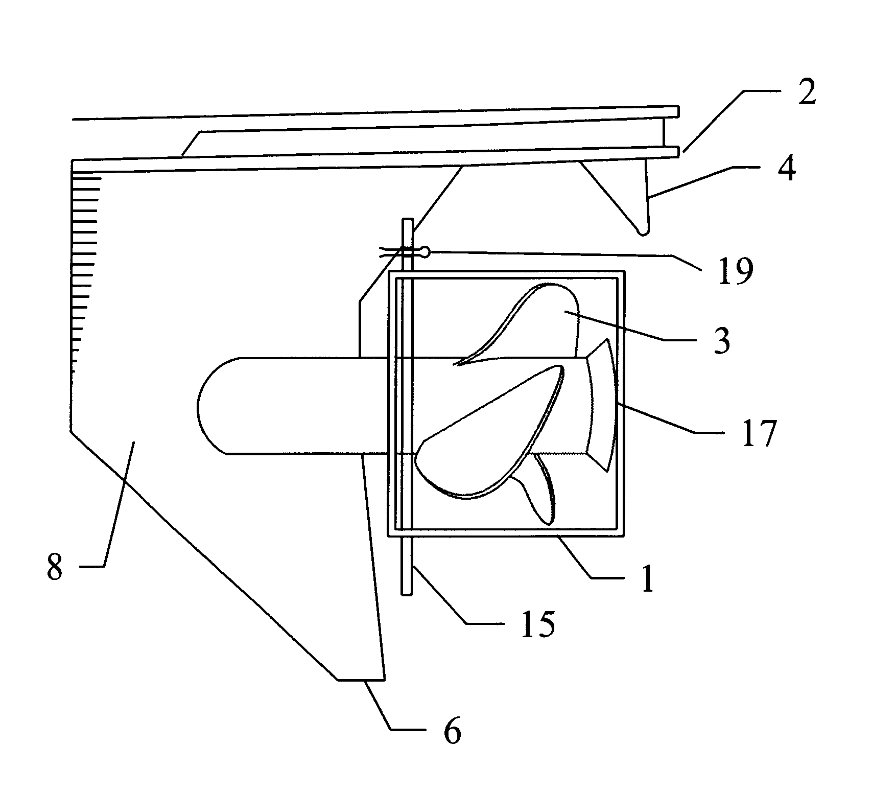
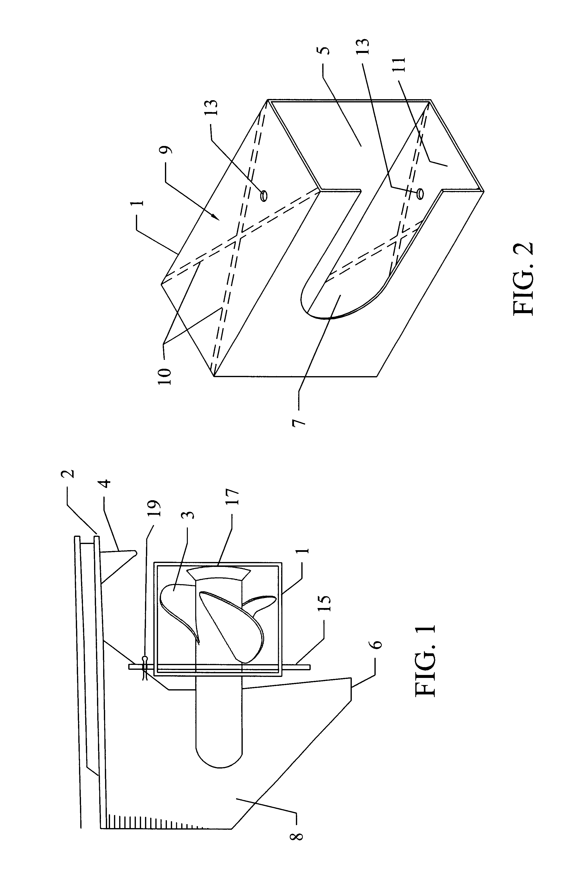
To slip the housing unit over the propeller, minimal longitudinal force is applied in either the starboard or the port direction. According to the present invention, the housing unit is easily slipped over a propeller of an outboard / outdrive motor that is located between three different structures: aft of the lower unit gear housing, below the anticavitation plate, and forward of the trim tab. This is particularly useful in that the user is not facing the propeller and is not liable to harm himself when attempting to secure the subject invention over a propeller. By slipping the housing unit over the propeller in a longitudinal direction, the propeller protector according to the present invention ensures that the user's hands do not get injured in the process of securing the housing unit over the propeller.
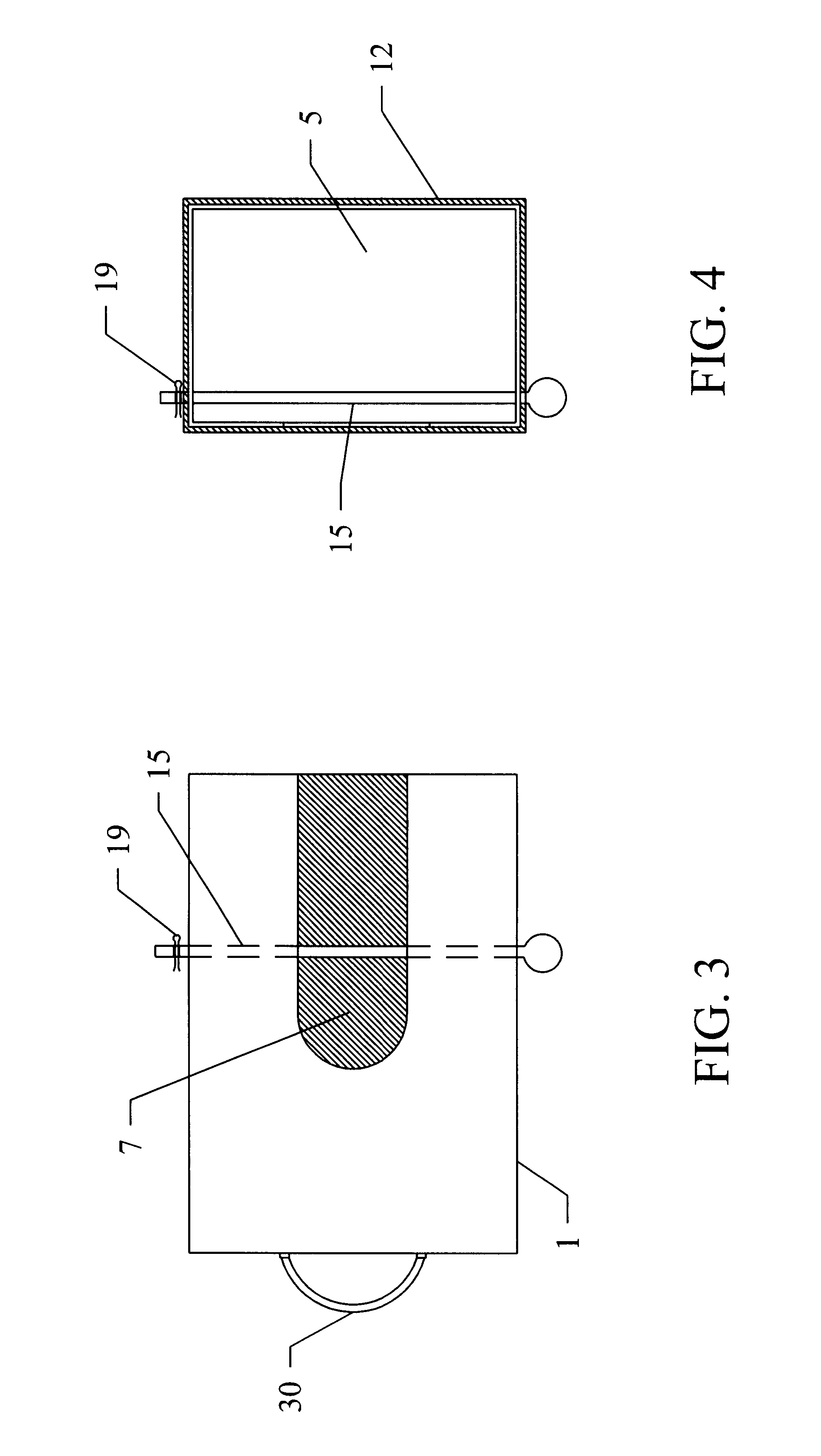
The housing unit may be constructed from a variety of materials and in a variety of shapes to ensure coverage over the propeller, so long as the shape accommodates the ability to longitudinally slip the housing unit over the propeller. For example, the housing unit may be composed of buoyant material to provide ease of recovery should the housing unit fall overboard. Where the shape of the housing unit more closely resembles the shape of the propeller, the greater the protection against detachment of the housing unit from the propeller due to vibration, wind, and water current.
In another embodiment of the present invention, the interior of the housing unit includes a cushioning means to protect the propeller from any force of impact generated by an object that strikes the housing unit. Yet another embodiment of the present invention provides a housing unit with reinforcement material surrounding the cut-away portion that accommodates the propeller shaft. Additional structural reinforcement known to the skilled artisan may be provided along the exterior surface of the housing unit. For example, the sides, front and back surfaces of the housing unit may be bent or include stiffening ribs to provide structural reinforcement. A further embodiment of the present invention includes a means for making the housing unit readily visible to individuals. Specifically, reflective tape or a warning sign may be secured to the exterior of a housing unit to ensure visibility of the propeller protector slipper for those vehicles following a boat in transit.

Problems solved by technology

Typically, the edges of propeller blades are very sharp and hazardous to any individuals within their vicinity, including boating passengers.
People boarding or disembarking from boats may injure themselves on the sharp edges of the propeller blades.
Such injuries often require stitches and are subject to infection based on the condition of the propeller and ambient water quality.
Unfortunately, fatal injuries such as drowning may also result from individual contact with unprotected propeller blades.
In such cases, the likelihood of injury resulting from contact with exposed propeller blades when swimming or wading in their vicinity is greatly increased.
Further, where swimmers are in water areas subject to tidal or general current, there is the possibility that the current will effect the swimmer's ability to evade contact with the propeller.
Therefore, entering into and exiting from the water, as well as conducting recreational activities in the water, are often hazardous activities when the outboard portion of the stem drive is raised or lowered.
Exposed propellers also present a risk of injury to those individuals outside of the water.
When the boat is docked, on a trailer, or out of the water in storage, individuals are subject to injury should they fall onto and cut themselves on the propeller blades.
In particular, children are especially prone to injuries when playing near the sharp blades of an exposed propeller protruding from a boat.
This can be hazardous to following vehicles as drivers may not appreciate how far the propeller and skeg project from the boat.
In addition, the position of the propeller is also hazardous to pedestrians who may bump into the propeller when walking or performing activities in the vicinity of the propeller.
Finally, exposed propellers and lower units are susceptible to damage when in shallow waters or in transit.
When a boat is docked or out of water in transit, the propeller is subjected to many elements (e.g. rocks or leaves) that damage the propeller blades.
Generally, the cost to repair or replace a propeller, an engine, or an outboard or outdrive is substantial.
The disadvantage of this bag is that it is pliable, requiring a user to adjust the mouth of the opening of the bag and bring their hands within close proximity if not having to actually touch the blades in order to place the bag over the propeller.
Further difficulties arise where the propeller is located beneath an anticavitation plate with a trim tab or where a skeg protrudes.
In situations where boat movement occurs due to tidal or general current, this bag is difficult to install and may result in injury to the user.
The design patent does not provide for ease of attachment and detachment of the shield because the shield is permanently affixed to the drive shaft.
U.S. Pat. No. 5,246,345 provides a cover that is unwieldy for underwater attachment to a propeller and has the potential for injuring the user when attempting to attach the cover to the propeller.
Finally, none of the current examples of propeller protectors contemplate a protector for a two bladed propeller.
Therefore, current propeller protective devices are difficult to install based on their general location above the skeg and beneath the anticavitation plate with trim tab, especially in waters where current is present.
In such instances, the user may be subject to harm when securing the device over a propeller on a moving boat.
By providing a means for longitudinally sliding the subject propeller slipper over a propeller from either port or starboard direction, user injuries are limited.

Method used


Image

  • Propeller protector slipper
  • Propeller protector slipper
  • Propeller protector slipper

Examples


Embodiment Construction

The present invention provides a propeller protector slipper to be applied to propellers of inboard and / or outboard motors. In a preferred embodiment, the propeller protector slipper according to the subject invention includes a housing unit to envelop a propeller and a means for securing the housing unit to maintain attachment over the propeller. Advantageously, the housing unit of the subject invention is safely and easily secured over a propeller by applying minimal longitudinal force to either the port or starboard side surface opposite the cut away side.

The terms "aft," "forward," "starboard," and "port," as used herein, are common nautical terms that identify various locations in relation to a nautical vessel.

The term "anticavitation plate" as used herein refers to a plate located above the propeller blades to prevent surface air from entering the blade area.

The term "trim tab" as used herein refers to one plane installed on the lower surface of the anticavitation plate of a b...


PUM


Abstract

Propeller protector slipper to be used on inboard and outboard motors of boats that are anchored, drifting, aground, docked, in storage, or out of water in transit. The propeller protector slipper ensures protection for the propeller from elements that cause pitting and damage to the propeller as well as minimizing propeller related injuries. The protector propeller slipper also provides a gage for projecting the distance of the propeller of a trailored boat from a following vehicle.

Description

BACKGROUND OF INVENTIONThe present invention concerns propeller protectors that are attached over propellers of outboard or inboard motors to protect individuals from accidental injury when in proximity to the propeller. In particular, the present invention relates to a propeller protector slipper that easily slides over and attaches to a propeller thus increasing the safety of the user and other individuals from the propeller blades, whether the propeller is up or down, trailoring, in water, or in storage. Advantageously, the protective slipper of the subject invention protects the propeller from damage.Typically, the edges of propeller blades are very sharp and hazardous to any individuals within their vicinity, including boating passengers. People boarding or disembarking from boats may injure themselves on the sharp edges of the propeller blades. Such injuries often require stitches and are subject to infection based on the condition of the propeller and ambient water quality. U...

Claims


Application Information

Patent Timeline
IPC IPC(8): B63H20/36B63H5/16B63H5/00B63H20/00
CPCB63H5/165B63H20/36
Inventor PITHER, ALLAN WALTER
Owner PITHER ALLAN WALTER
Learn More