Eureka AIR delivers breakthrough ideas for toughest innovation challenges, trusted by R&D personnel around the world.

Electromagnetic wave filter apparatus without degrading radiation pattern of antenna

a filter apparatus and electromagnetic wave technology, applied in the direction of antennas, antenna details, radiating element housings, etc., can solve the problems of difficult circuit output power, propagation loss becomes serious, and diffraction propagation cannot be expected for 60 ghz-band electromagnetic waves, so as to ensure the area coverage of wireless communication equipment and avoid radiation characteristics degradation

Active Publication Date: 2014-02-18
PANASONIC CORP
View PDF15 Cites 0 Cited by
  • Summary
  • Abstract
  • Description
  • Claims
  • Application Information

AI Technical Summary

Benefits of technology

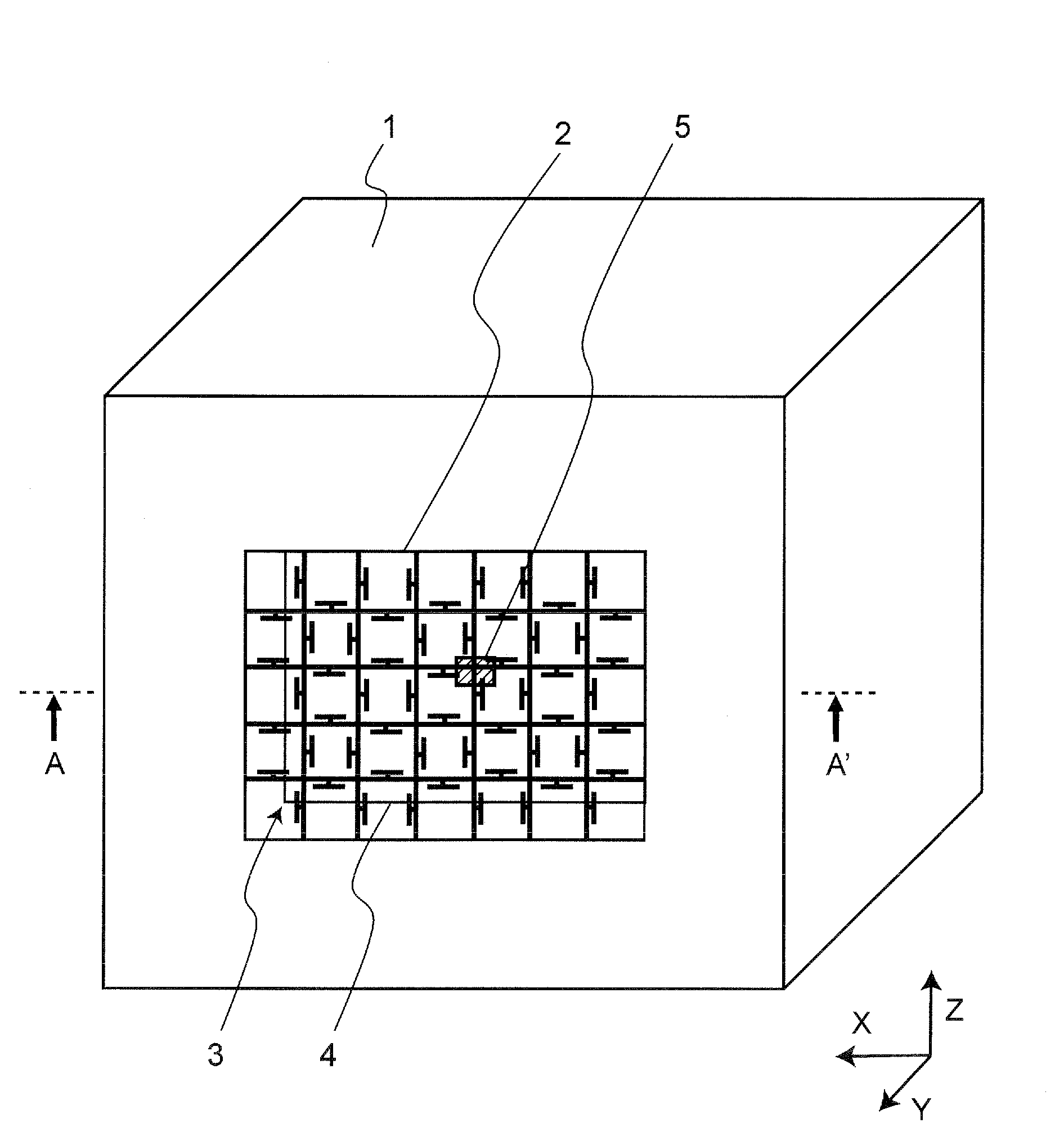
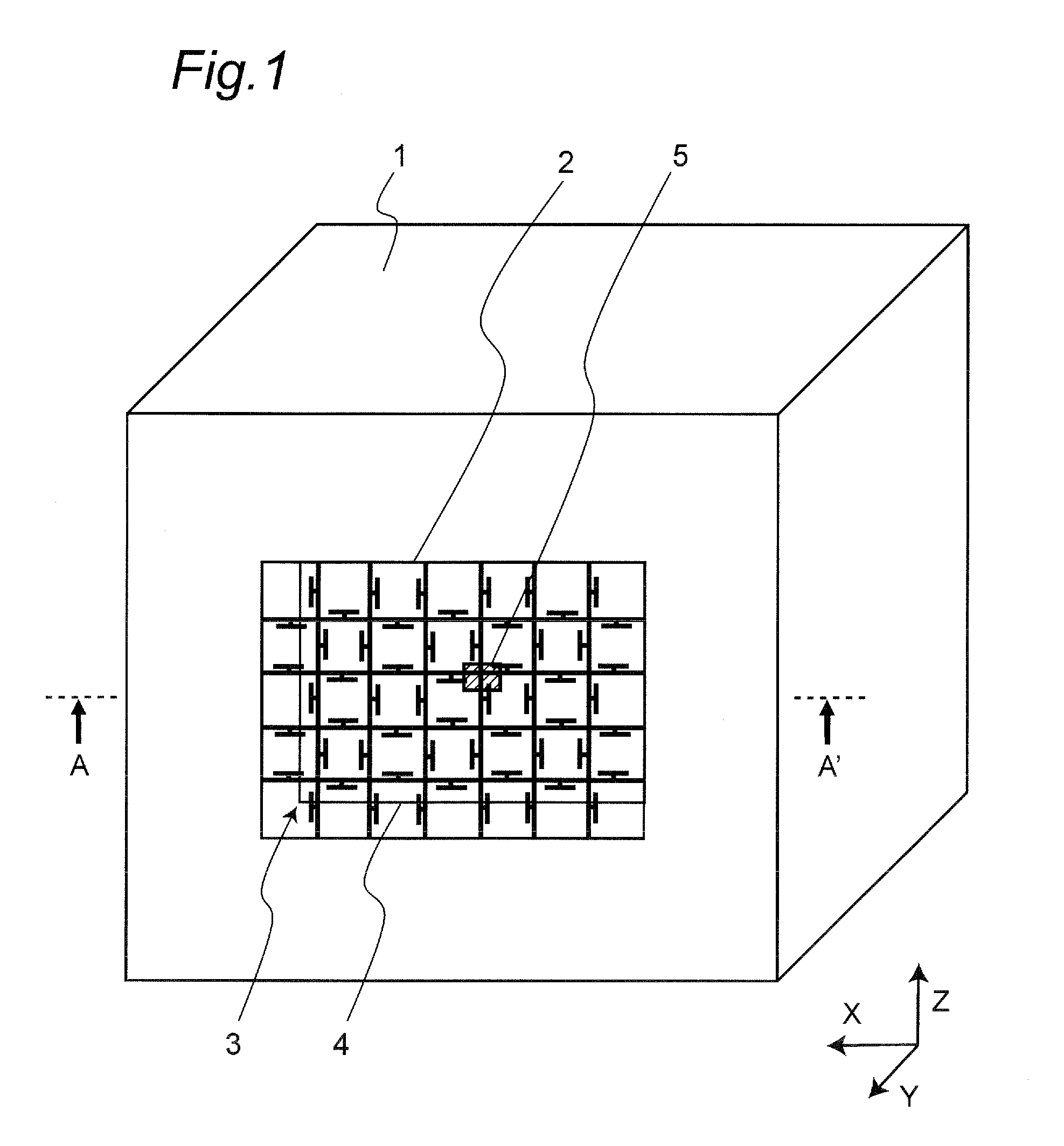
[0029]According to the electromagnetic wave filter apparatus of the present invention, it is possible to obtain regions on the strip conductors in which no radio frequency current with a certain frequency is generated, by providing the strip conductors with the bandstop filters, and thus avoid a degradation in the radiation characteristics of the radiated electromagnetic waves passing through the screen portion, which is a problem of prior art electromagnetic wave filter apparatuses.
[0030]According to the electromagnetic wave filter apparatus of the present invention, firstly, even when an antenna apparatus is shielded by the electromagnetic wave filter apparatus, it is possible to maintain the radiation characteristics of the antenna apparatus at a certain frequency, thus ensuring the area coverage of wireless communication equipment. Secondly, the electromagnetic wave filter apparatus can suppress undesired noise components radiated from the antenna apparatus and passing through the electromagnetic wave filter apparatus, and low-frequency electromagnetic waves of external disturbing waves incoming to the antenna apparatus and passing through the electromagnetic wave filter apparatus.

Problems solved by technology

Although an active circuit operable in the 60 GHz band has been implemented as one chip by using the CMOS technologies with fine processing, it is difficult to increase the circuit output power because of a low drive voltage for transistors in the circuit.
In addition, diffraction propagation can not be expected for 60 GHz-band electromagnetic waves, and thus, it is necessary to ensure a line of sight between a transmitter and a receiver.
However, in the millimeter-wave band with a shorter wavelength, the propagation loss becomes serious as compared to that of the microwave band, and thus, it is necessary to steer the antenna beam while maintaining a very high antenna gain.

Method used


Image

  • Electromagnetic wave filter apparatus without degrading radiation pattern of antenna
  • Electromagnetic wave filter apparatus without degrading radiation pattern of antenna
  • Electromagnetic wave filter apparatus without degrading radiation pattern of antenna

Examples


example 1

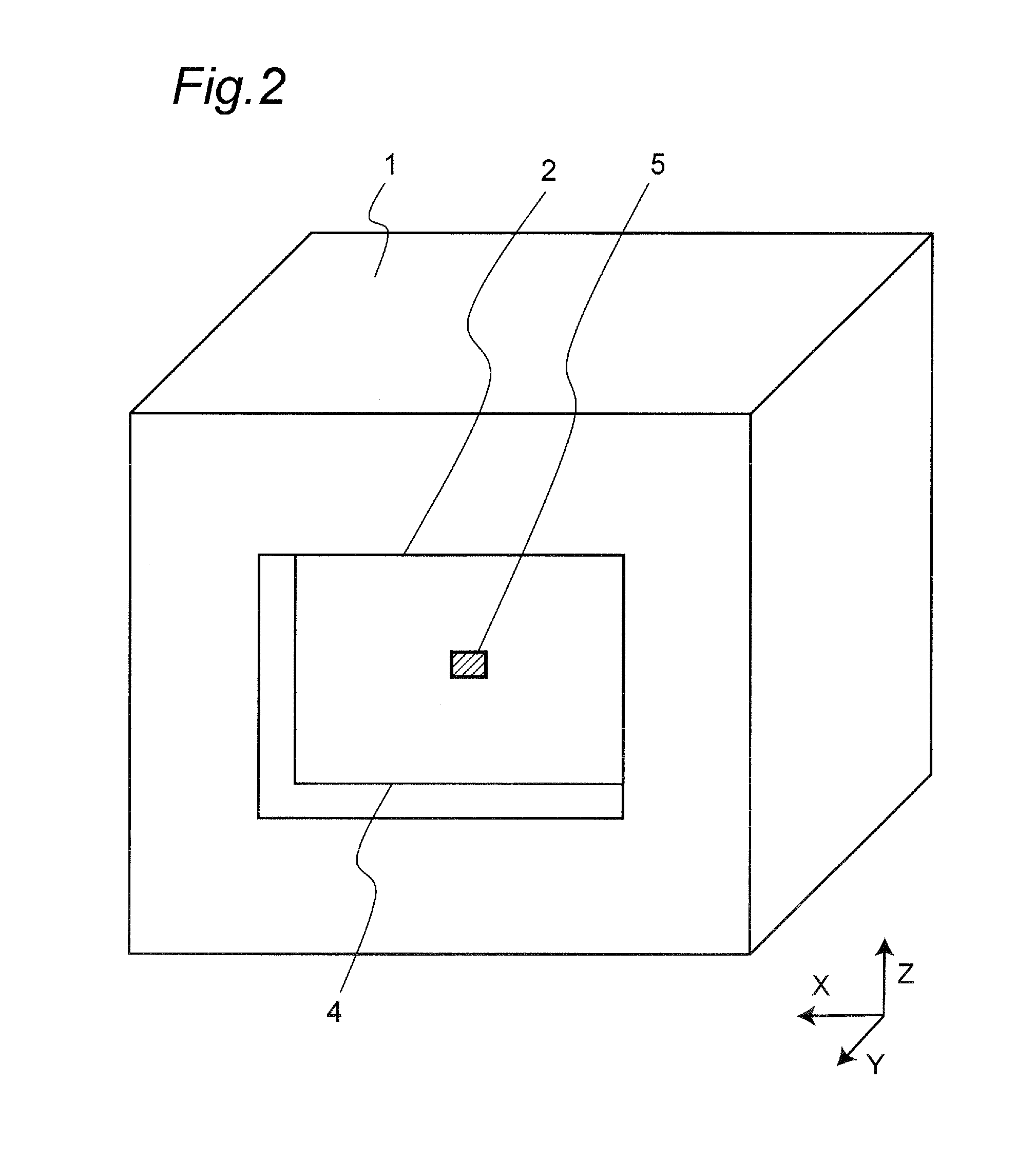
[0083]For the purpose of demonstrating the advantageous effects of the present invention, a radome of a first implementation example based on the electromagnetic wave filter apparatus 3B of FIG. 7, and radomes of second and third implementation examples based on the electromagnetic wave filter apparatus 3 of FIG. 3 were fabricated. In addition, radomes of first to fifth comparison examples were fabricated as typical examples of the prior art with which the implementation examples were compared. Those parameters other than the main configuration parameters of the electromagnetic wave filter apparatus were the same for all the fabricated implementation examples and comparison examples. In the following description, XYZ coordinates shown in FIG. 1, etc. are referenced.

[0084]As an antenna element 5 to be contained in a shield conductor 1, a vertical polarization patch antenna formed on an antenna substrate 4 made of alumina was used. The antenna element 5 had a size of 0.8 mm×0.95 mm. T...


PUM


Abstract

An electromagnetic wave filter apparatus includes: a shield conductor; a shield aperture provided in the shield conductor; a plurality of strip conductors, each of which is connected to the shield conductor at both ends thereof, and which divide the shield conductor into a plurality of apertures; and a plurality of stub conductors provided at intervals on each of the strip conductors. Each of the stub conductors prevents a current with a predetermined frequency from flowing through a corresponding strip conductor due to an electromagnetic wave with the predetermined frequency passing through the electromagnetic wave filter apparatus. Thus, the electromagnetic wave filter apparatus passes the electromagnetic wave with the predetermined frequency without exerting a substantial influence on radiation of the electromagnetic wave with the predetermined frequency.

Description

TECHNICAL FIELD[0001]The present invention relates to an electromagnetic wave filter apparatus, which is required when providing electronic equipment with an antenna apparatus for transmitting and receiving radio frequency analog signals or digital signals in the microwave band and the millimeter-wave band, etc. The present invention relates to an electromagnetic wave filter apparatus, e.g., in electronic equipment with wireless communication capability for video transmission, the electromagnetic wave filter apparatus being capable of suppressing undesired noise radiation so that noise generated from the inside of the electronic equipment does not radiate to outer space, in particular, without degrading the radiation pattern at a frequency used in the wireless communication capability, and the present invention also relates to a radome with such an electromagnetic wave filter apparatus.BACKGROUND ART[0002]In recent years, the wireless technologies for video transmission have been wi...

Claims


Application Information

Patent Timeline
Patent Type & Authority Patents(United States)
IPC IPC(8): H01Q1/42H01Q15/02
CPCH01Q15/0053H01Q15/0013H01Q15/0006H01Q3/46H05K9/006
Inventor KANNO, HIROSHI
Owner PANASONIC CORP
Why Eureka
Eureka Blog
Learn More