

Rare earth magnet and method therefor
a rare earth magnet and magnet technology, applied in the field can solve the problems of difficult application of magnets to motors with medium to high output, and significant lowering of etc., to achieve the effect of increasing the electric resistance significantly lowering the magnetic characteristics of rare earth magnets, and medium to high outpu
- Summary
- Abstract
- Description
- Claims
- Application Information
AI Technical Summary
Benefits of technology
Problems solved by technology
Method used
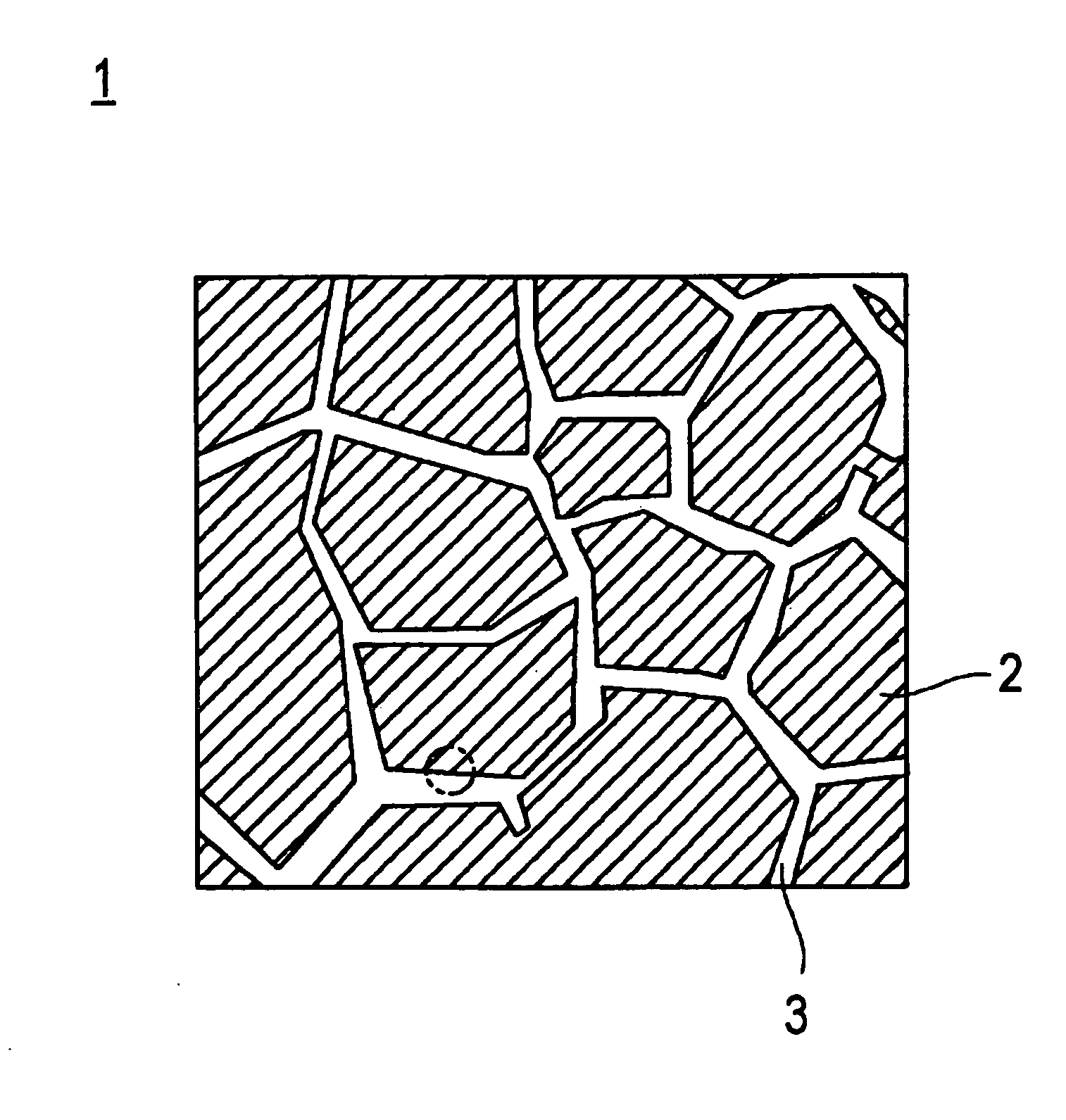
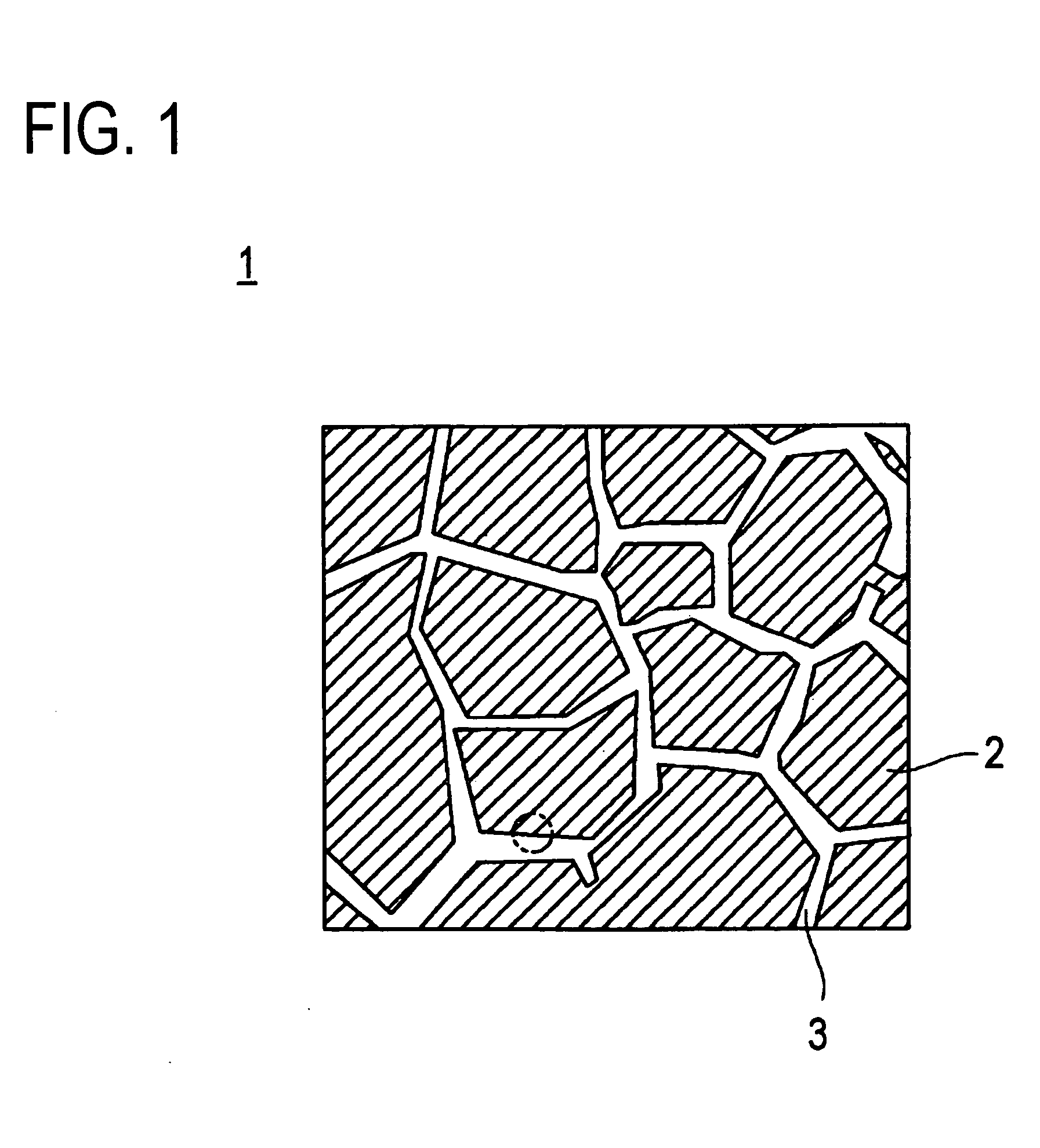
Image

Examples
example 1
[0060] As magnet powder for rare earth magnet, Nd—Fe—B type anisotropic magnet powder, prepared by using a known HDDR method, were used. The procedure for producing the magnet powder for rare earth magnet is as follows. First, an ingot with composition of Nd12.6FebalCo17.4B6.5Ga0.3Al0.5Zr0.1 was prepared. This ingot was homogenized by holding at 1120° C. for 20 hours. The homogenized ingot was hold in hydrogen atmosphere while increasing the temperature from room temperature to 500° C., then up to 850° C., followed by holding under vacuum atmosphere at 850° C. and cooling to obtain an alloy having recombined cluster texture (crystal grains) showing a fine ferromagnetic phase. This alloy was pulverized under argon gas atmosphere by use of a jaw crasher and a brown mill to obtain magnet powder for rare earth magnet having the average particle diameter of not larger than 425 μm.
[0061] Tb4O7 powder as terbium oxides and the magnet powder for rare earth magnet were mixed to obtain a mix...
example 2
[0065] As magnet powder for rare earth magnet, Nd—Fe—B type anisotropic magnet powder, produced by using a known HDDR method in similar way to Example 1, were used. As a method for producing the rare earth magnet, the following method was adopted; terbium triisopropoxide, which is terbium alkoxide, was coated on the surface of the magnet powder for rare earth magnet, polycondensating the resultant by hydrolysis and heat treatment of terbium triisopropoxide, and thus obtained magnet powder for rare earth magnet were used, at the surface of which terbium oxide is bound. Detailed procedure is as follows:
[0066] (1) 200 g of terbium triisopropoxide as terbium alkoxide was dissolved by adding dewatered hexane as an organic solvent in a glove box filled with argon gas, where the dew point is not higher than −80° C., and then liquid for terbium surface treatment was prepared in the total volume of 1000 ml.
[0067] (2) 180 mL of the liquid for terbium surface treatment was added into 1000 g ...
example 3
[0073] As magnet powder for rare earth magnet, Nd—Fe—B type anisotropic magnet powder, produced by using a known HDDR method in similar way to Example 1, were used. As a method for producing the rare earth magnet, the following method was adopted; terbium triisopropoxide, which is terbium alkoxide, was coated on the surface of the magnet powder for rare earth magnet, polycondensating the resultant by hydrolysis and heat treatment of terbium triisopropoxide, and thus obtained magnet powder for rare earth magnet were used, at the surface of which terbium oxide is bound. Detailed procedure is as follows:
[0074] (1) 150 g of terbium triisopropoxide as the terbium alkoxide was dissolved by adding dewatered tetrahydrofuran as an organic solvent in a glove box filled with argon gas, where the dew point is not higher than −80° C., and then liquid for terbium surface treatment was prepared in the total volume of 1000 ml.
[0075] (2) 360 mL of the liquid for terbium surface treatment was added...
PUM
| Property | Measurement | Unit |
|---|---|---|
| diameter | aaaaa | aaaaa |
| size | aaaaa | aaaaa |
| size | aaaaa | aaaaa |
Abstract
Description
Claims
Application Information