
Precision-guided hypersonic projectile weapon system

a projectile and precision technology, applied in direction controllers, launch/towing gear, transportation and packaging, etc., can solve the problems of increased system complexity, increased cost, and increased system complexity

Inactive Publication Date: 2003-09-02
RAYTHEON CO
View PDF22 Cites 25 Cited by
  • Summary
  • Abstract
  • Description
  • Claims
  • Application Information

AI Technical Summary

Benefits of technology

Enables accurate delivery of a tungsten rod penetrator at hypersonic velocity with at least one-meter accuracy and sufficient energy to destroy armored targets while simplifying the system and reducing costs by allowing direct ballistic paths and minimizing inert weight and drag.

Problems solved by technology

Unfortunately, the rocket has heretofore left a large exhaust plume which has been impenetrable by optical, laser or infrared (IR) band energy to provide guidance commands from the launch platform.
Millimeter wave radar can penetrate the plume but usually does not offer sufficient resolution to provide the degree of guidance accuracy required.
These design concessions result in increased system complexity, compromised performance, and higher cost.

Method used


Image

  • Precision-guided hypersonic projectile weapon system
  • Precision-guided hypersonic projectile weapon system
  • Precision-guided hypersonic projectile weapon system

Examples


Embodiment Construction

An illustrative embodiment will now be described with reference to the accompanying drawings to disclose the advantageous teachings of the present invention.

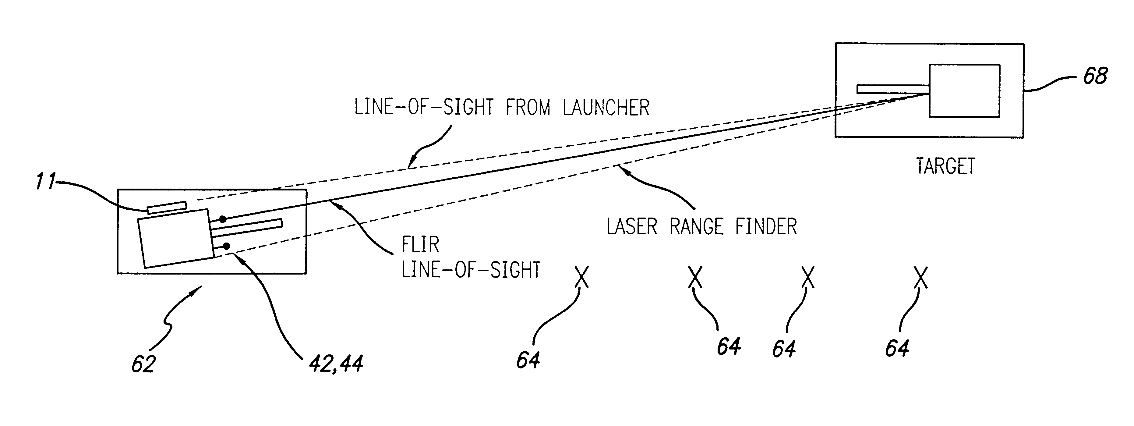
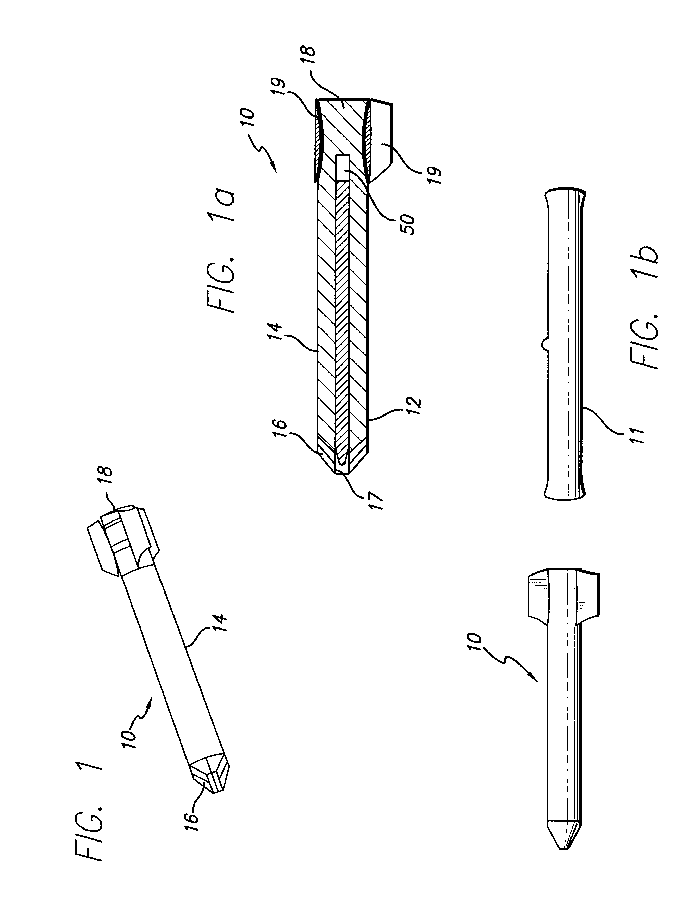
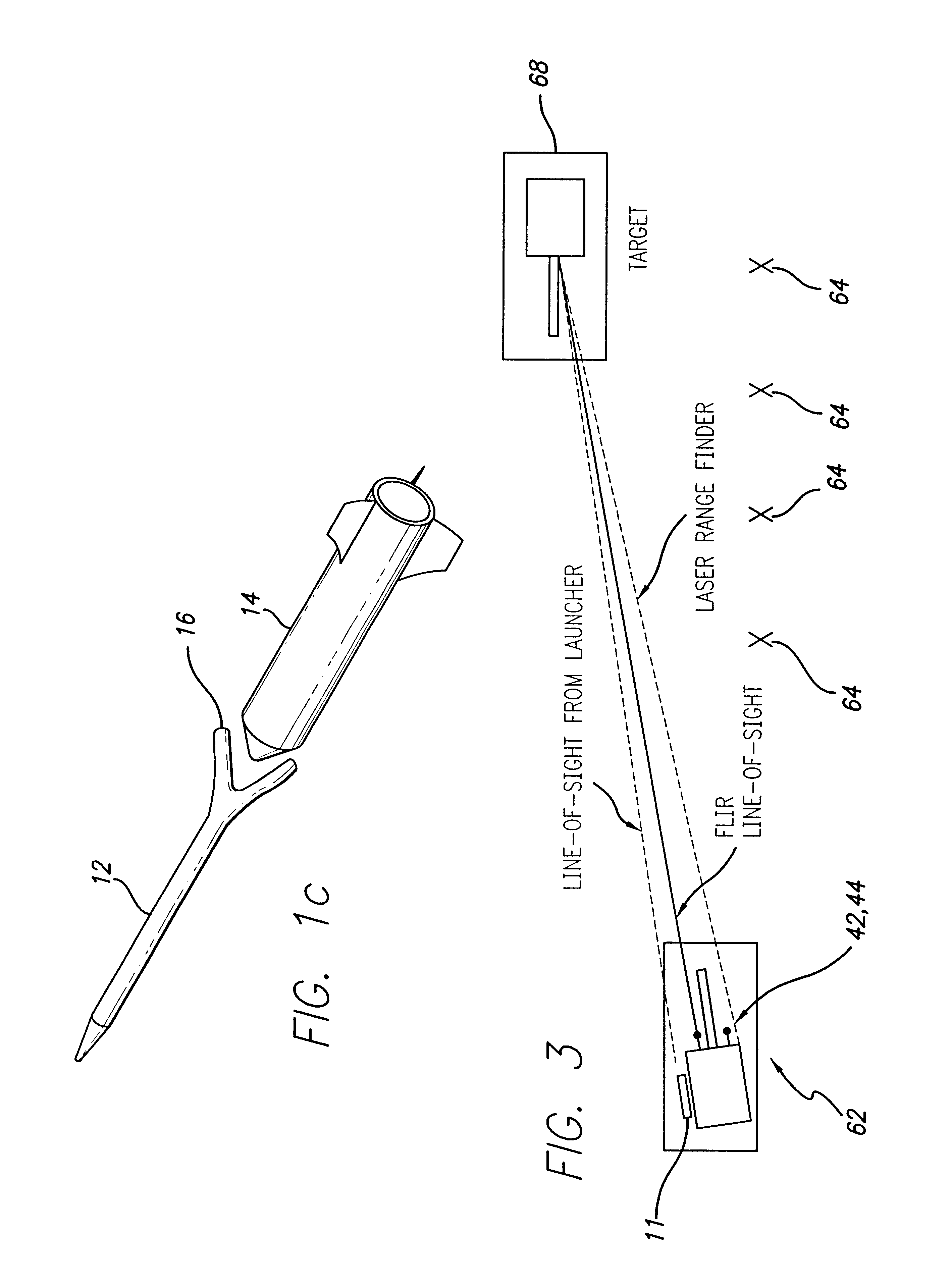
FIG. 1 is a perspective view of an illustrative implementation of a hypervelocity missile in accordance with the teachings of the present invention. FIG. 1a is a sectional side view of a missile incorporating the teachings of the present invention. In the illustrative embodiment, the system is similar to the system disclosed in U.S. Pat. No. 5,005,781 entitled IN-FLIGHT RECONFIGURABLE MISSILE CONSTRUCTION, issued on Apr. 9, 1991 by Baysinger et al., the teachings of which are incorporated herein by reference. As shown in FIGS. 1 and la, the missile 10 includes a tungsten rod or projectile 12. (Those skilled in the art will appreciate that the present invention is not limited to the material construction of the rod 12.) The tungsten rod 12 is contained within a rocket motor case 14. Stabilization fins 16 for the rod 12 are locate...


PUM


Abstract

A precision-guided hypersonic projectile weapon system. The inventive system includes a first subsystem for determining a target location and providing data with respect thereto. A second subsystem calculates trajectory to the target based on the data. The projectile is then launched and guided in flight along the trajectory to the target. In the illustrative application, the projectile is a tungsten rod and the first subsystem includes a forward-looking infrared imaging system and a laser range finder. The second subsystem includes a fire control system. The fire control system includes an optional inertial measurement unit and predicts target location. The projectile is mounted in a missile launched from a platform such as a vehicle. After an initial burn, the missile launches the projectile while in flight to the target. The missile is implemented with a rocket with a guidance system and a propulsion system. In accordance with the present teachings, the guidance system includes a transceiver system mounted on the projectile. The transceiver system includes a low-power continuous wave, millimeter wavelength wave emitter. A system is included at the launch platform for communicating with the projectile. The platform system sends a blinking command to the projectile and measures the round trip delay thereof to ascertain the range of the projectile. Velocity is determined by conventional Doppler techniques or differentiation. Azimuth and elevation are then determined by a monopulse antenna on the launch platform. As a consequence, the platform ascertains the location of the projectile and the impact point thereof. The platform generates a command to the projectile which is received by the projectile and used to actuate control surfaces to adjust the trajectory and impact point thereof as necessary.

Description

1. Field of InventionThis invention relates to missile guidance systems and methods. Specifically, the present invention relates to systems and methods for guiding hypersonic projectiles.2. Description of the Related ArtThe U.S. Army has shown that a tungsten long-rod penetrator delivering in excess of 10 megajoules of energy at hypersonic velocity to the armor of a tank can penetrate the armor and destroy the tank. This has involved boosting the rod to hypersonic speed using a rocket. For guidance, hypervelocity anti-tank weapon prior art has focused on the use of laser beam-rider guidance technology. Unfortunately, the rocket has heretofore left a large exhaust plume which has been impenetrable by optical, laser or infrared (IR) band energy to provide guidance commands from the launch platform. Thus the target is obscured when guidance is required.Millimeter wave radar can penetrate the plume but usually does not offer sufficient resolution to provide the degree of guidance accura...

Claims


Application Information

Patent Timeline
Patent Type & Authority Patents(United States)
IPC IPC(8): F41G7/20F41G7/30F41G9/00
CPCF41G7/305
Inventor SCHNEIDER, ARTHUR J.KLESTADT, RALPH H.FAULKNER, DAVID A.
Owner RAYTHEON CO
Learn More