Fluid pump mechanism for use in existing helical gearsets

a technology of helical gears and pump mechanisms, which is applied in the direction of liquid fuel engines, machines/engines, drip or splash lubrication, etc., can solve the problem that the gears used in these gear pumps are not designed to transfer larger torques

Inactive Publication Date: 2003-09-09
FORD GLOBAL TECH LLC
View PDF26 Cites 39 Cited by
  • Summary
  • Abstract
  • Description
  • Claims
  • Application Information

AI Technical Summary

Problems solved by technology

The gears used in these gear pumps are not designed to transfer larger amounts of torque, which is necessary in the drivetrain.

Method used


Image

  • Fluid pump mechanism for use in existing helical gearsets
  • Fluid pump mechanism for use in existing helical gearsets
  • Fluid pump mechanism for use in existing helical gearsets

Examples


Embodiment Construction

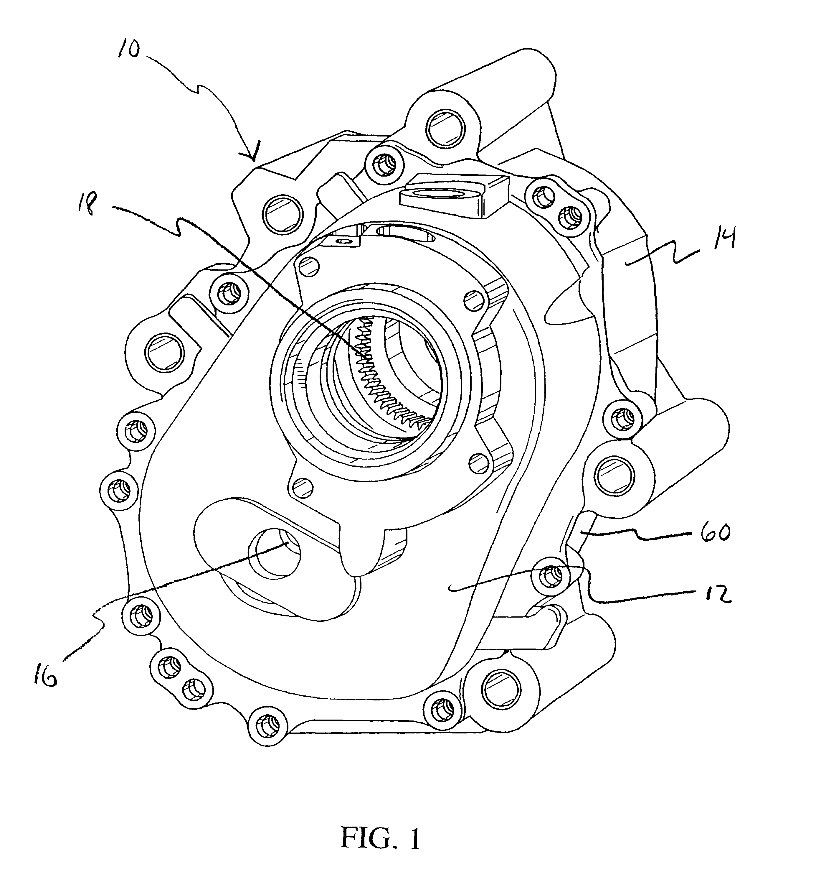
Referring in combination to FIGS. 1 and 2, a power take-off unit 10 for use with the present invention is shown. FIG. 1 shows the power take-off unit 10 with the cover 12 in place over a chamber 14. The cover 12 and chamber 14 preferably have a seal between them to form a sealed casing. This sealed casing allows the interior of the power take-off unit 10 to contain a fluid bath (not shown in FIG. 1). The fluid can be any fluid known in the art useful in a drivetrain system or other vehicular system. Some examples are lubricant or cooling fluid.

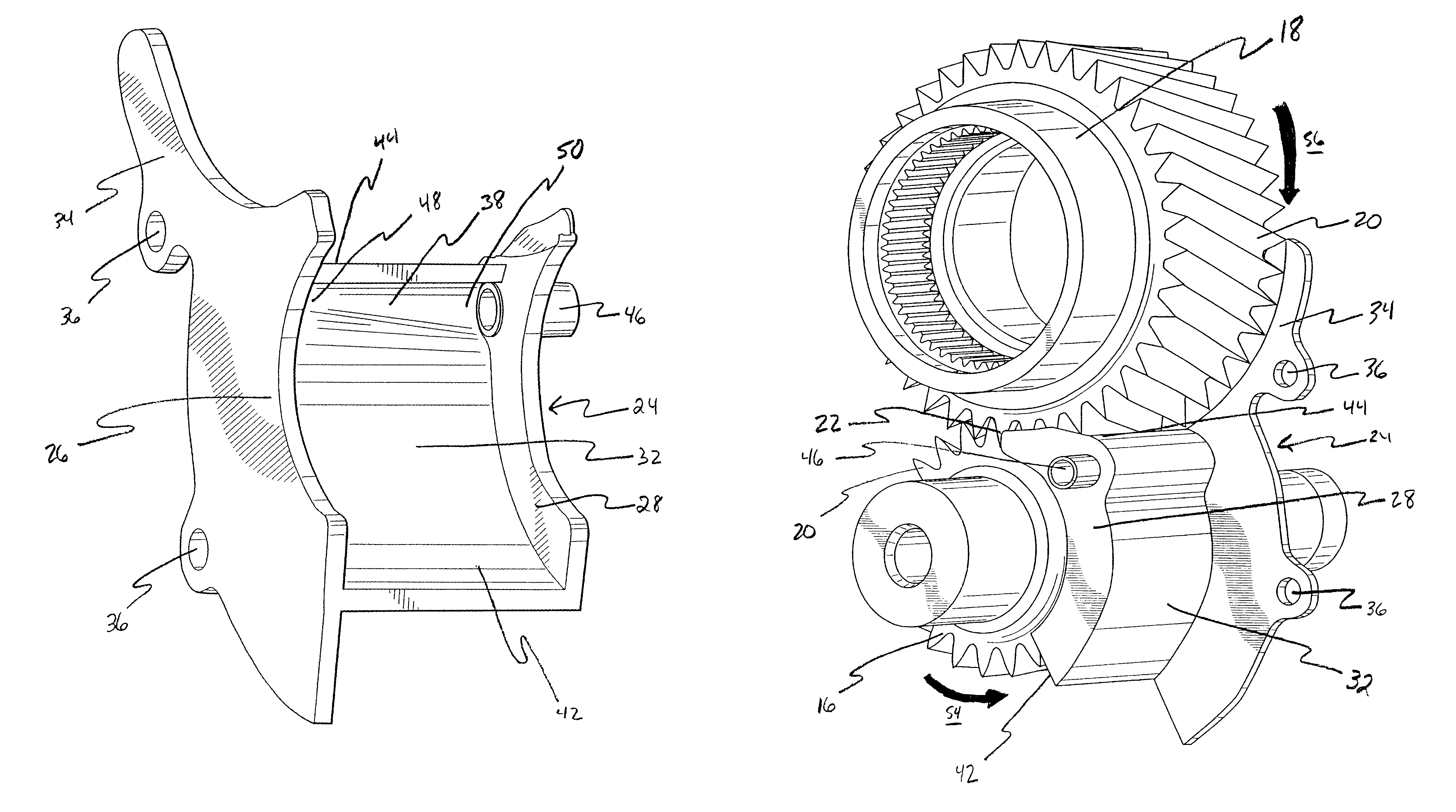
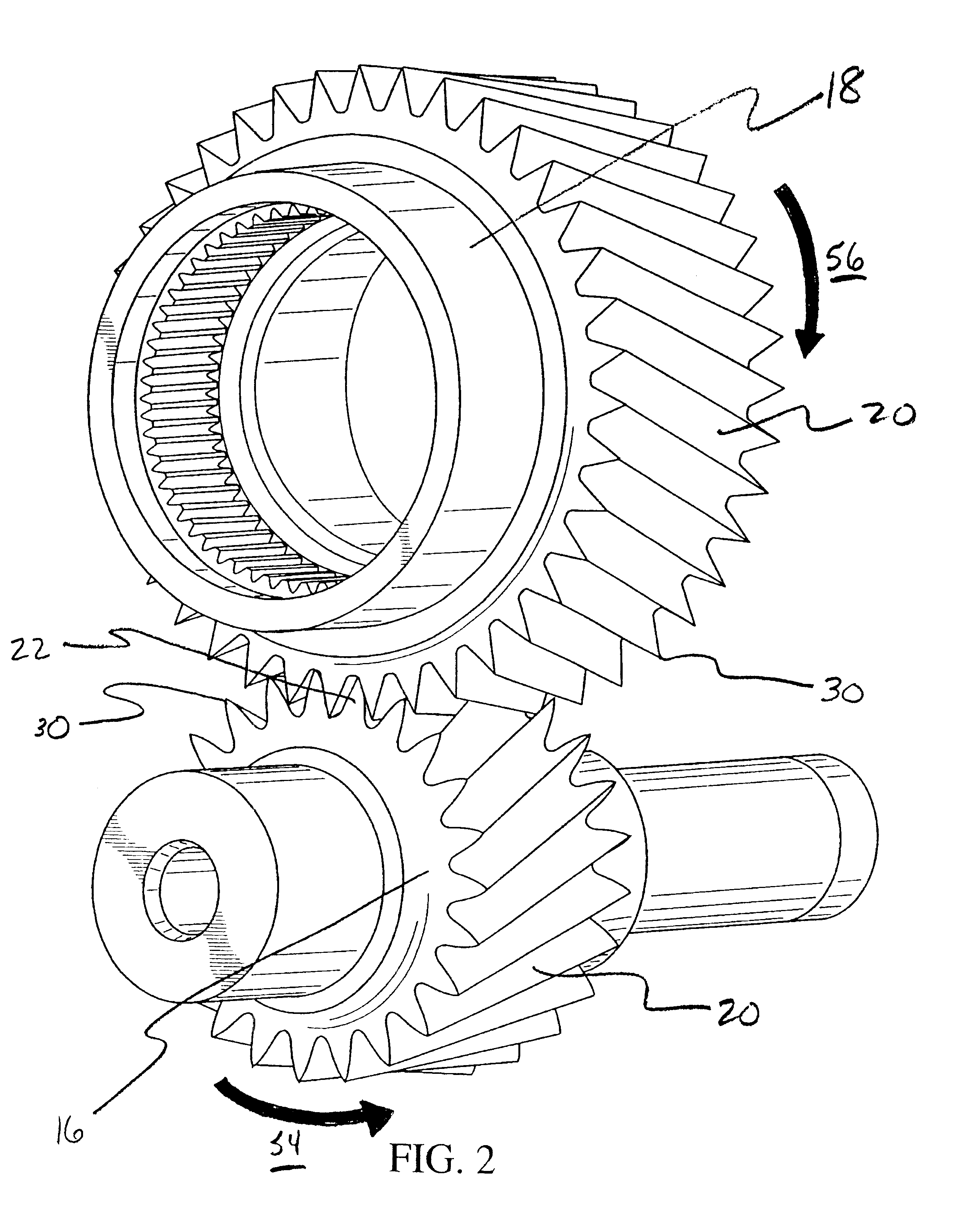
The power take-off unit 10 preferably contains a first helical gear 16 and a second helical gear 18. The first 16 and second 18 helical gears are shown in FIG. 2 outside of the power take-off unit 10 for clarity. The teeth 20 of the first 16 and second 18 helical gears preferably intermesh in an area 22 between the first 16 and second 18 helical gears.

In the preferred embodiment of the present invention, a cowling is provided in order to maint...


PUM


Abstract

A fluid pump cowling for attachment to at least a pair of helical drivetrain gears having teeth and lands. The cowling has a pair of sidewalls adapted to extend at least partially over the lands of a first of the pair of drivetrain gears and a curved sump wall extending between the sidewalls that corresponds generally to the outermost circumference of the first gear. A sump channel is defined between the sidewalls on the sump wall adjacent a distal end of the sump wall. The sump channel has a generally frustoconical shape and leads to a fluid outlet opening defined in one of the sidewalls. The cowling is positioned such that the teeth of the pair of helical gears mesh in an area in fluid communication with the sump channel to create an area of high fluid pressure upon rotational movement of the gears with a fluid.

Description

The invention relates generally to the field of gear pumps. In particular, this invention relates to a cowling for use in existing helical gear sets for implementing a fluid pumping mechanism.DESCRIPTION OF THE RELATED ARTGear pumps have been utilized to pump fluid from one area to another. In a gear pump, a pressure differential is formed at the points of convergence and divergence of the gear teeth of the intermeshing gears. If fluid is trapped between the gear teeth, the fluid will be forced out of the spaces between the gear teeth by this pressure differential.Gear pumps typically are only used to pump fluid, and do not make up a part of the drivetrain of a vehicle. The gears used in these gear pumps are not designed to transfer larger amounts of torque, which is necessary in the drivetrain.The gear pump concept has also been used to keep gears lubricated in a drivetrain. One such system is disclosed in U.S. Pat. No. 2,645,305. One gear in this system is partially located in a c...

Claims


Application Information

Patent Timeline
Patent Type & Authority Patents(United States)
IPC IPC(8): F04C2/00F04C2/16F04C2/08
CPCF04C2/082F04C2/16Y10T74/19991F16H57/0495F16H57/0423
Inventor SZCZEPANSKI, GERALD S.ADLER, JONATHAN M.
Owner FORD GLOBAL TECH LLC
Why Eureka
Try Eureka