Three-phase connector for electric vehicle drivetrain

a technology of three-phase connectors and electric vehicles, applied in the direction of coupling contact members, coupling device connections, conductor screwing into other, etc., can solve the problems of large package, large effort required for assembly, and inability to simply thread wires, so as to reduce the size and cost of the part, the effect of reducing the effort required

Inactive Publication Date: 2005-05-10
SIEMENS VDO AUTOMOTIVE CORP
View PDF13 Cites 80 Cited by
  • Summary
  • Abstract
  • Description
  • Claims
  • Application Information

AI Technical Summary

Benefits of technology

[0007]It is a feature and advantage of the present invention to provide a three-phase connector that carries all three phases in one connector, while keeping all the phases properly isolated from each other and from the motor case.
[0008]To achieve the stated and additional features, advantages and objects, an embodiment of the present invention provides a three-phase connector that carries all three phases in one connector and keeps all the phases properly isolated from each other and the motor case. The three-phase connector has three separate metal inserts which act as each phase carrying electrical current to a three-phase induction motor. The three inserts are all molded into one plastic housing, which reduces the size and cost of the part, and reduces the effort required to assemble the drivetrain.
[0009]An embodiment of the present invention provides a three-phase connector, for example, for an electric vehicle drivetrain, utilizing two or more, and preferably three electrically conductive connector components, that are spaced from one another and supported in an over molding of electrically insulating material covering each of the connector components, except for upper and lower exposed ends of the connector components, and also forming a supporting flange. First and second ones of the connector components are spaced farther apart from one another than they are from a third connector component that is disposed, for example, between them. The first and second connector components extend above the flange with their respective exposed upper ends offset in different planes than the exposed upper end of the third connector component. The first and second connector components also extend below the flange with their respective exposed lower ends disposed in different planes than the third connector component.
[0010]In addition, the upper exposed ends of the first and second connector components are disposed a different and preferably shorter distance above the flange than the exposed upper end of the third connector component, and the respective lower exposed ends of the first and second connector components are disposed a different and preferably greater distance below the flange than the exposed lower end of the third connector component. Further, each of the connector components has an upper portion that extends a pre-defined distance above the flange and a lower portion that extends a greater distance below the flange than the pre-defined distance above the flange.
[0011]An electrically insulating material, such as nylon, is used for the over molding, and each connector component is made of an electrically conducting metal, such as tellurium copper, that is machined and over molded with the electrically insulating material. Each connector component is drilled at its upper and lower ends and tapped internally to receive a threaded bolt, for example, for a busbar or a lead. Each connector component has an exterior wall with one or more undercuts that provide an anchor for the over molding material. The flange is provided with openings to receive fasteners for attaching the flange to a housing. An alternate embodiment includes, for example, partitions formed by the over molding that extend upward from the flange between each of the first and second connector components and the third connector component.

Problems solved by technology

It is not possible to simply thread the wires for the three phases through an opening in the electric motor housing because the current carried through the phase connections is very high, such as 350-400 amps.
The resulting package was large, costly, and required significant effort to assemble.

Method used


Image

  • Three-phase connector for electric vehicle drivetrain
  • Three-phase connector for electric vehicle drivetrain
  • Three-phase connector for electric vehicle drivetrain

Examples


Embodiment Construction

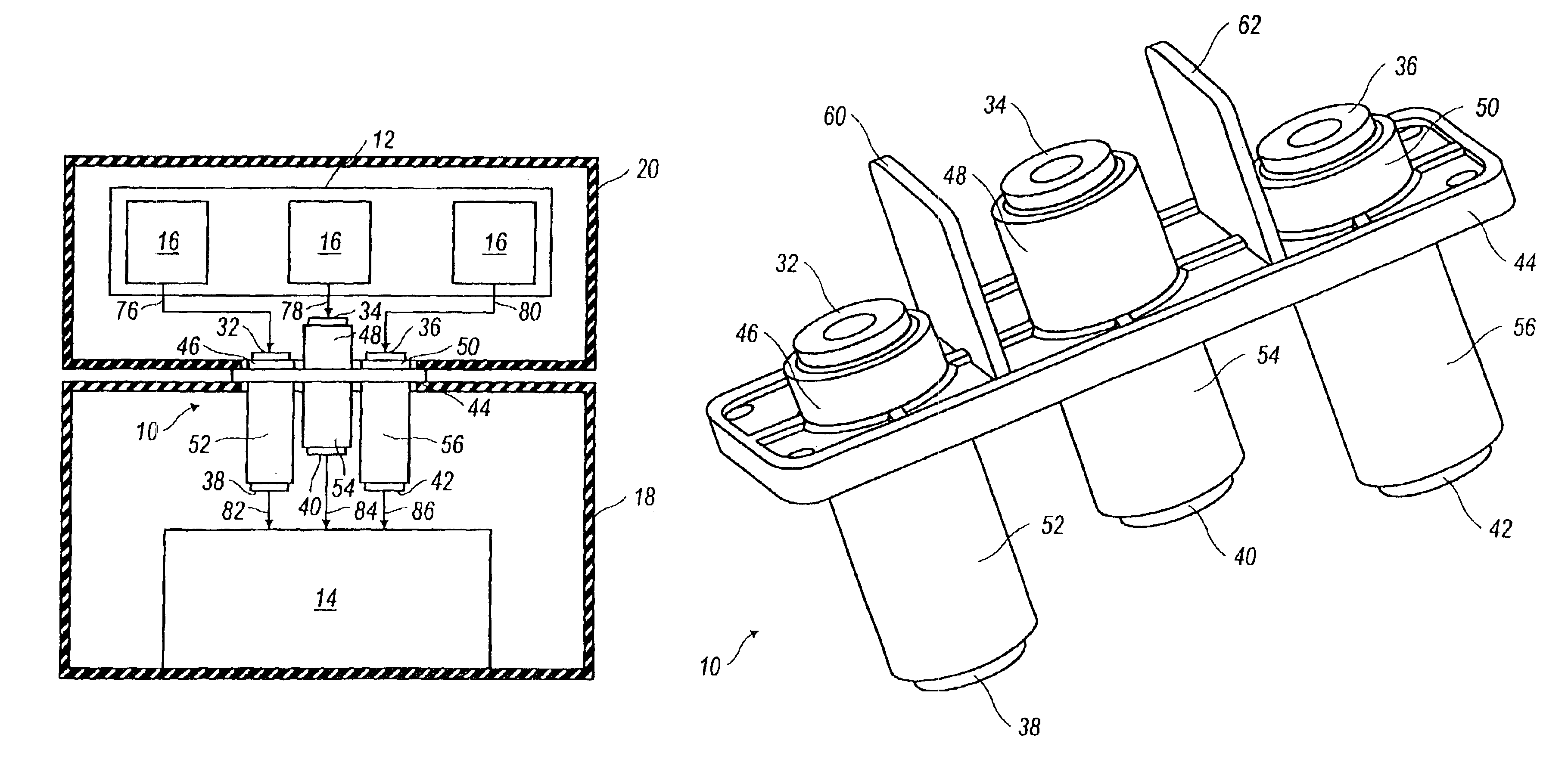
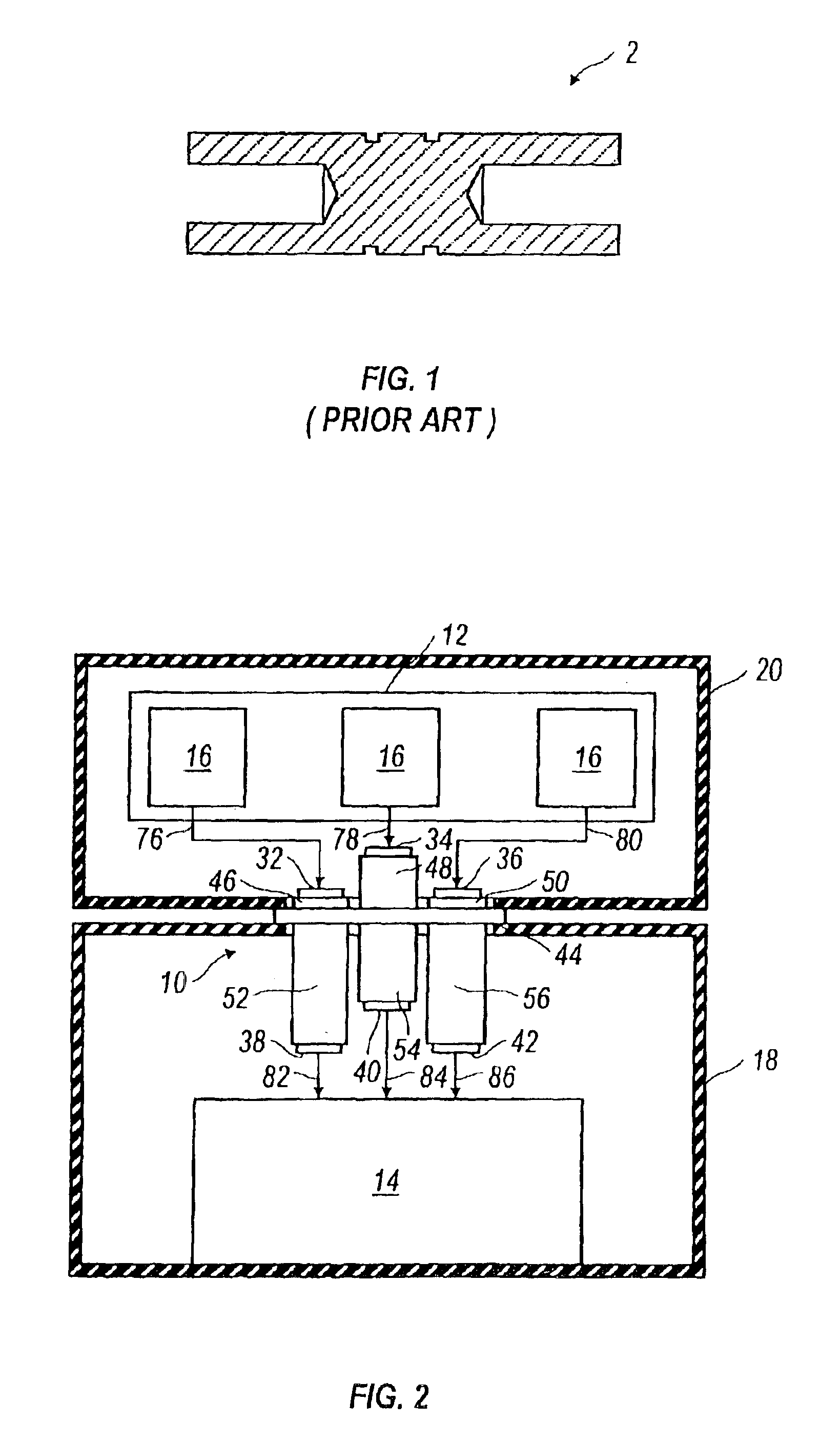
[0019]An embodiment of the present invention will now be described in detail with reference to the accompanying drawings wherein like reference numerals will be used to describe like components. Referring to FIG. 2, the three-phase connector 10 makes the connection between the inverter 12 and the electric motor 14. Disposed between the three IGBT's 16 of the inverter 12 and the three-phase connector 10 is a busbar (not more particularly shown), which connects the IGBT's 16 of the inverter 12 to the three-phase connector 10. The three-phase connector 10 sits on a casting 18, which is the housing for the electric motor 14, and the inverter 12 also has a housing or casting 20. The task of the three-phase connector 10 is to get the three-phase current through those two castings 18, 20 to the windings for the electric motor 14.

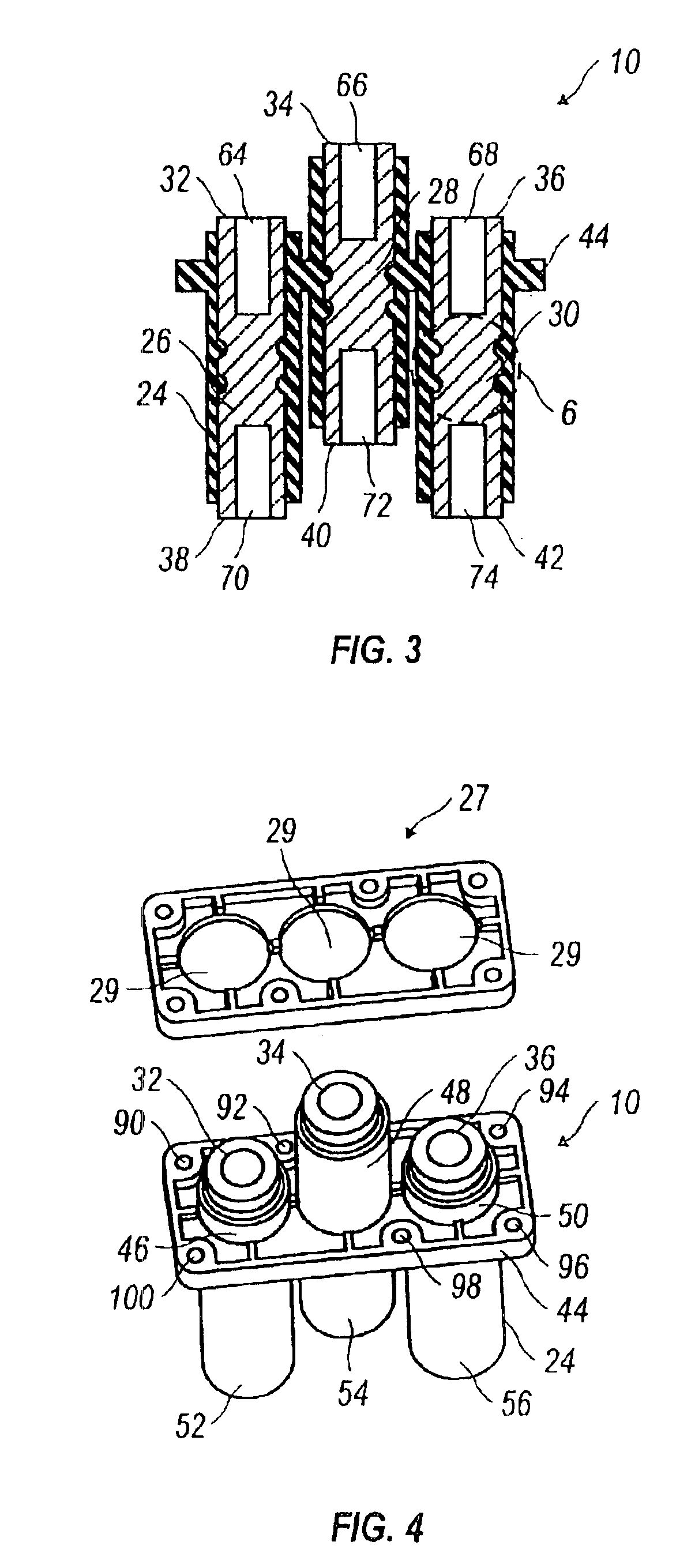
[0020]Referring to FIGS. 2-4, the three phases are isolated at least in part with a nylon over molding 24 of the three-phase connector 10, which covers three metal...


PUM


Abstract

A three-phase connector carries all three phases in one connector and keeps the phases properly isolated from each other and the motor case. The three-phase connector has metal connector components that are spaced from one another and supported in a nylon over molding covering each of the connector components, except for upper and lower exposed ends of the connector components, which are each drilled and tapped to receive bolts. First and second connector components extend above and below a flange of the three-phase connector with their respective exposed upper and lower ends offset in different planes than the exposed upper and lower ends of the third connector component.

Description

CROSS-REFERENCE TO RELATED APPLICATION[0001]This application is a continuation of U.S. patent application Ser. No. 09 / 682,976 filed Nov. 5, 2001, now U.S. Pat. No. 6,572,416 now allowed, which application is incorporated herein by reference in its entirety.BACKGROUND OF INVENTION[0002]1. Field of the Invention[0003]The present invention relates generally to the field of electric machines, and more particularly to a three-phase connector for an electric vehicle drivetrain.[0004]2. Background of the Invention[0005]Phase connectors are connectors which carry current, for example, from the internally gated bipolar transistors (IGBT's) of an inverter to an electric motor. The IGBT is the power transistor in the inverter and generates the sine wave for the three-phase current. It is not possible to simply thread the wires for the three phases through an opening in the electric motor housing because the current carried through the phase connections is very high, such as 350-400 amps. In ca...

Claims


Application Information

Patent Timeline
Patent Type & Authority Patents(United States)
IPC IPC(8): H01R4/56H01R13/405
CPCH01R13/405H01R4/56H01R2201/10
Inventor PATWARDHAN, AJAY VFRANKLIN, JOHN
Owner SIEMENS VDO AUTOMOTIVE CORP
Why Eureka
Try Eureka