Passive tracking system and method

a passive tracking and transmitter technology, applied in the direction of direction finders, radio wave direction/deviation determination systems, instruments, etc., can solve the problems of slow location fix, additional antennas, and additional circuitry, and achieve the effect of slowing down the fixation speed, not necessarily operating indoors, and increasing the difficulty of tracking

Inactive Publication Date: 2003-09-09
ADMINISTATOR OF NAT AERONAUTICS & SPACE ADMINSTRATION U S GOVERNMENT AS REPRESENTED BY THE +1
View PDF10 Cites 9 Cited by
  • Summary
  • Abstract
  • Description
  • Claims
  • Application Information

AI Technical Summary

Problems solved by technology

Previous options for this application included utilizing GPS location devices but these require additional circuitry, additional antennas, do not necessarily operate indoors, and may be slow to obtain a location fix.
However radar is nonpassive, requires high power, and also requires a recognizable signature at the target for identification.
However, the ESPRIT technique is based on relatively complicated mathematics.
The complexity of these requirements effectively renders the ESPRIT technique unacceptable for many applications requiring low weight and power and small size.
The array processing problem addressed is that of signal parameter and waveform estimation utilizing data collected by an array of sensors.
The above prior art does not disclose a system that uses a herein disclosed technique in one preferred embodiment for extracting a direction vector from a pair of phase shifts.
Moreover, the prior art does not disclose the herein disclosed technique for extracting the phase difference between a transmitter and receiver, which in one preferred embodiment may provide a noncoherent demodulation scheme, and then using the phase difference to detect the location of the transmitter.

Method used


Image

  • Passive tracking system and method
  • Passive tracking system and method
  • Passive tracking system and method

Examples


Embodiment Construction

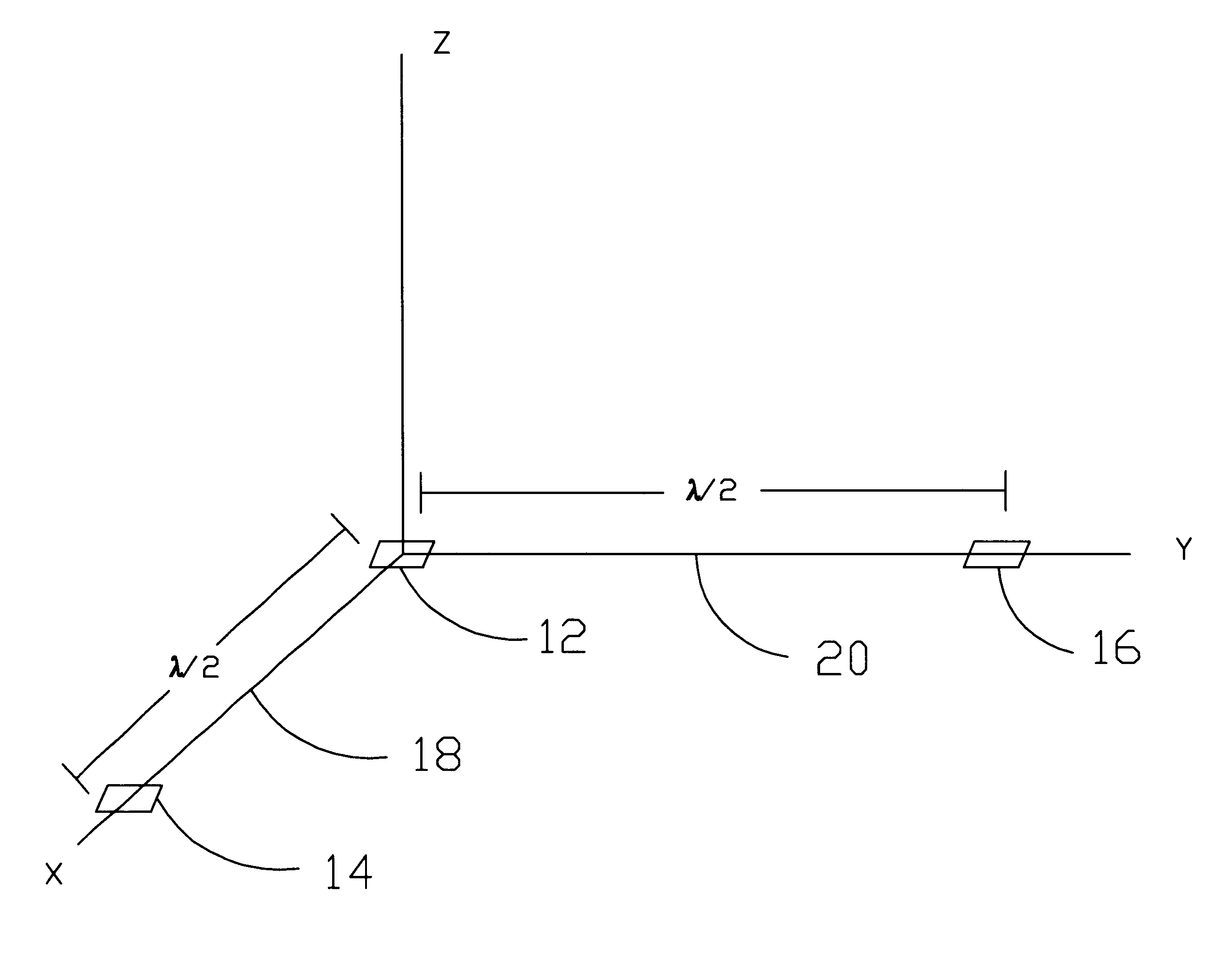
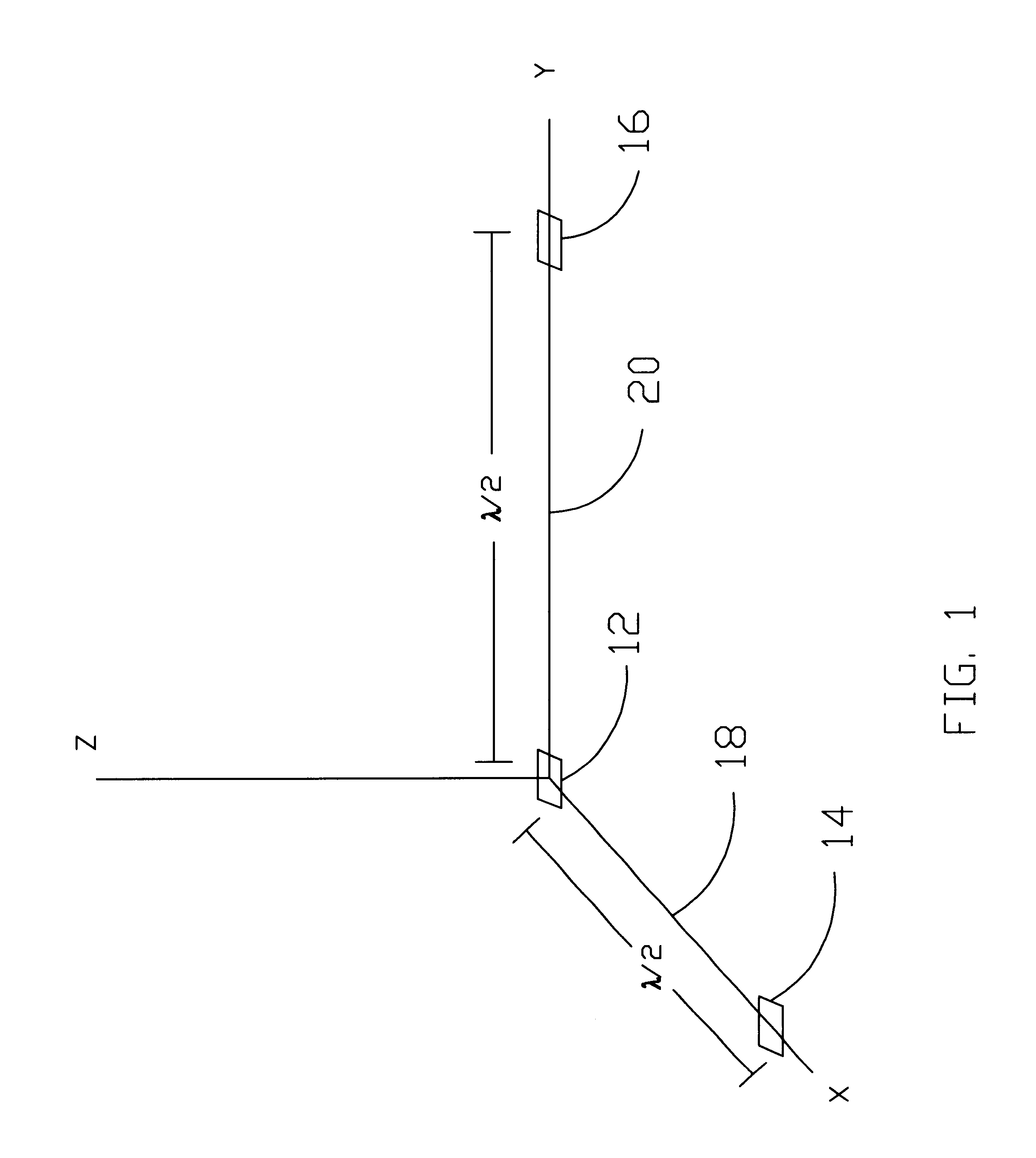
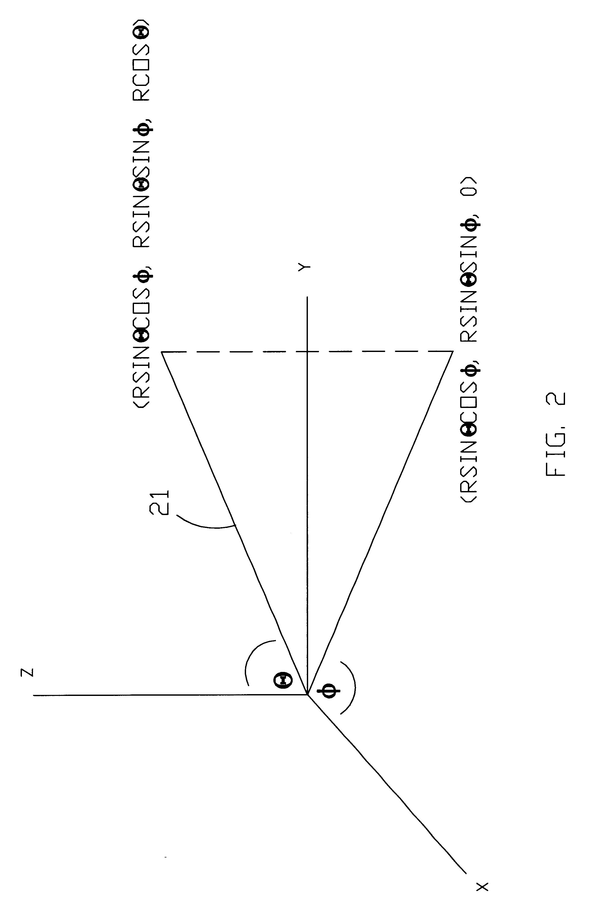
The present invention provides a quickly operating, inexpensive, system and method for locating a transmitter in 3-D space (in x, y, and z). Location times may typically be determined real time (less than one second). The accuracy of location is comparable to that of GPS location systems and is typically at least within tens of feet but may potentially be considerably more precise depending on the particular mode of operation as discussed hereinafter. In a preferred embodiment, the transmitter may be a standard communications transmitter, such as a cell phone or other communications transmitter, and it is desired to determine the location thereof. Thus, the transmitter sends a standard data-modulated signal, which could be any type of communications signal. An advantage of the present invention is that a special distress signal is not required for operation of the invention so that the present invention can simply be used as an inexpensive, add-on feature to any communications syste...


PUM


Abstract

System and methods are disclosed for passively determining the location of a moveable transmitter utilizing a pair of phase shifts at a receiver for extracting a direction vector from a receiver to the transmitter. In a preferred embodiment, a phase difference between the transmitter and receiver is extracted utilizing a noncoherent demodulator in the receiver. The receiver includes an antenna array with three antenna elements, which preferably are patch antenna elements spaced apart by one-half wavelength. Three receiver channels are preferably utilized for simultaneously processing the received signal from each of the three antenna elements. Multipath transmission paths for each of the three receiver channels are indexed so that comparisons of the same multipath component are made for each of the three receiver channels. The phase difference for each received signal is determined by comparing only the magnitudes of received and stored modulation signals to determine a winning modulation symbol.

Description

ORIGIN OF THE INVENTIONThe invention described herein was made by employee(s) of the United States government and may be manufactured and used by or for the Government of the United States of America for governmental purpose without payment of any royalties thereon or therefor.1. Field of the InventionThe present invention relates generally to signal tracking systems and, more specifically, to a passive system for tracking / locating a transmitter.2. Background of the InventionDetermining the location and / or tracking a moveable transmitter is useful for many purposes. For instance, there frequently exists an urgent need for locating the source of an emergency 911 telephone call from a mobile phone. Previous options for this application included utilizing GPS location devices but these require additional circuitry, additional antennas, do not necessarily operate indoors, and may be slow to obtain a location fix.Other tracking requirements might include tracking an astronaut in space du...

Claims


Application Information

Patent Timeline
Patent Type & Authority Patents(United States)
IPC IPC(8): G01S5/04G01S3/14G01S3/46H04B1/707H04B1/7085
CPCG01S3/46G01S5/0205G01S5/04H04B1/7085G01S5/06
Inventor ARNDT, G. DICKEYNGO, PHONG H.CHEN, HENRY A.PHAN, CHAU T.BOURGEOIS, BRIAN A.DUSL, JOHNHILL, BRENT W.
Owner ADMINISTATOR OF NAT AERONAUTICS & SPACE ADMINSTRATION U S GOVERNMENT AS REPRESENTED BY THE
Why Eureka
Try Eureka