Automatic tyre removal and mounting device and tyre removal machines equipped therewith

a technology of mounting device and tyre, which is applied in the direction of tyre repairing, vehicle components, transportation and packaging, etc., can solve the problem of being subject to the risk of accidents

Inactive Publication Date: 2003-09-16
NEXION SPA
View PDF9 Cites 39 Cited by
  • Summary
  • Abstract
  • Description
  • Claims
  • Application Information

AI Technical Summary

Benefits of technology

An object of the present invention is to overcome the drawbacks of the known art within the framework of a rational and reliable solution, which does not require the operator to intervene actively during the removal of the tyre from the wheel rim, or during the opposite operation.

Problems solved by technology

In addition, the manual intervention of the operator means that he is subjected to the risk of accidents, as he has to work with moving equipment and in contact with lubricated surfaces.

Method used


Image

  • Automatic tyre removal and mounting device and tyre removal machines equipped therewith
  • Automatic tyre removal and mounting device and tyre removal machines equipped therewith
  • Automatic tyre removal and mounting device and tyre removal machines equipped therewith

Examples


Embodiment Construction

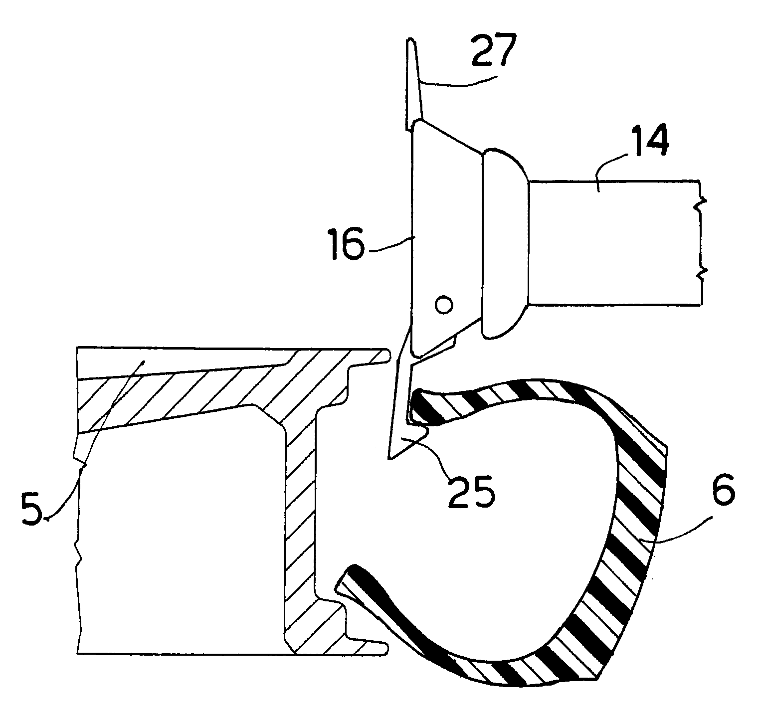
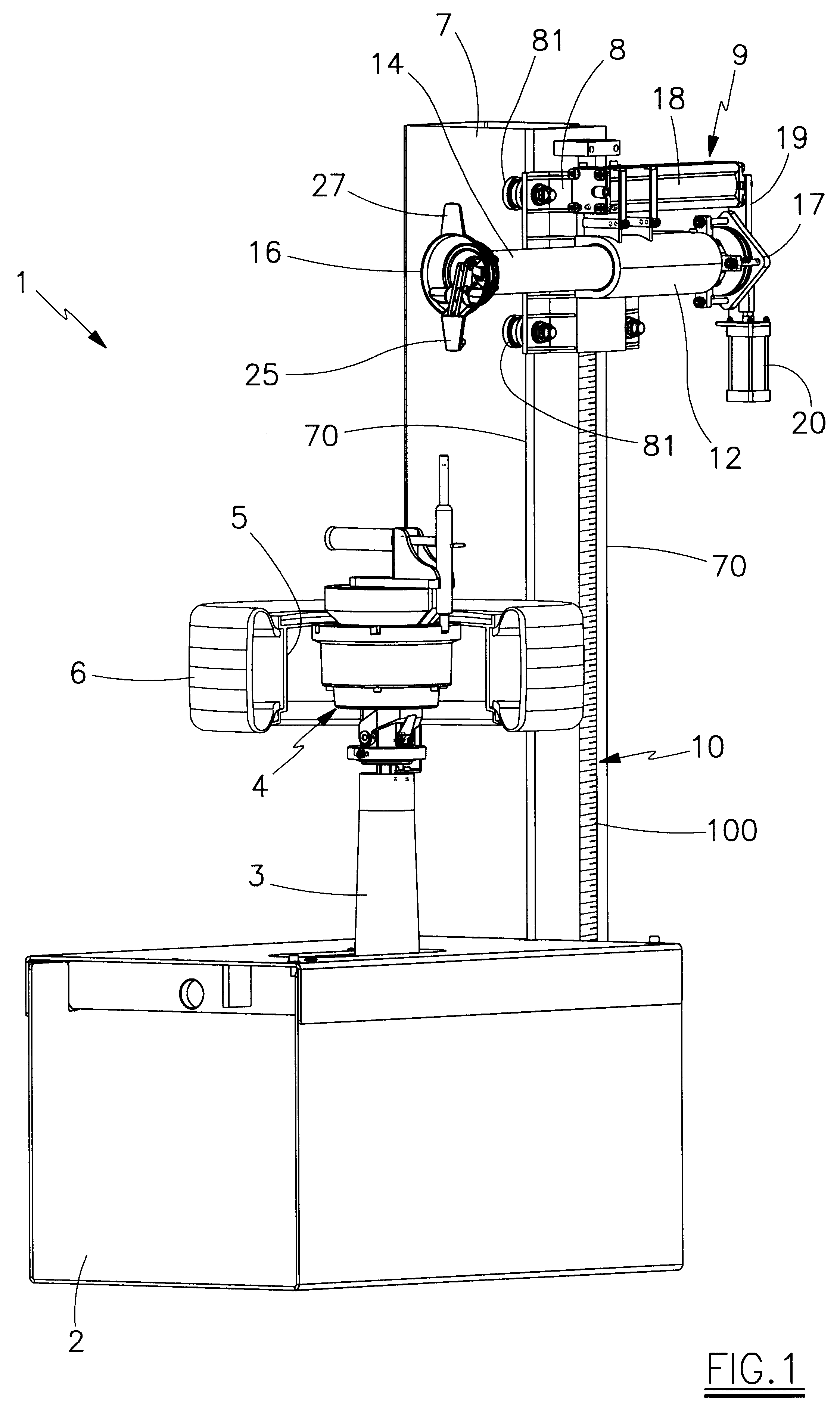
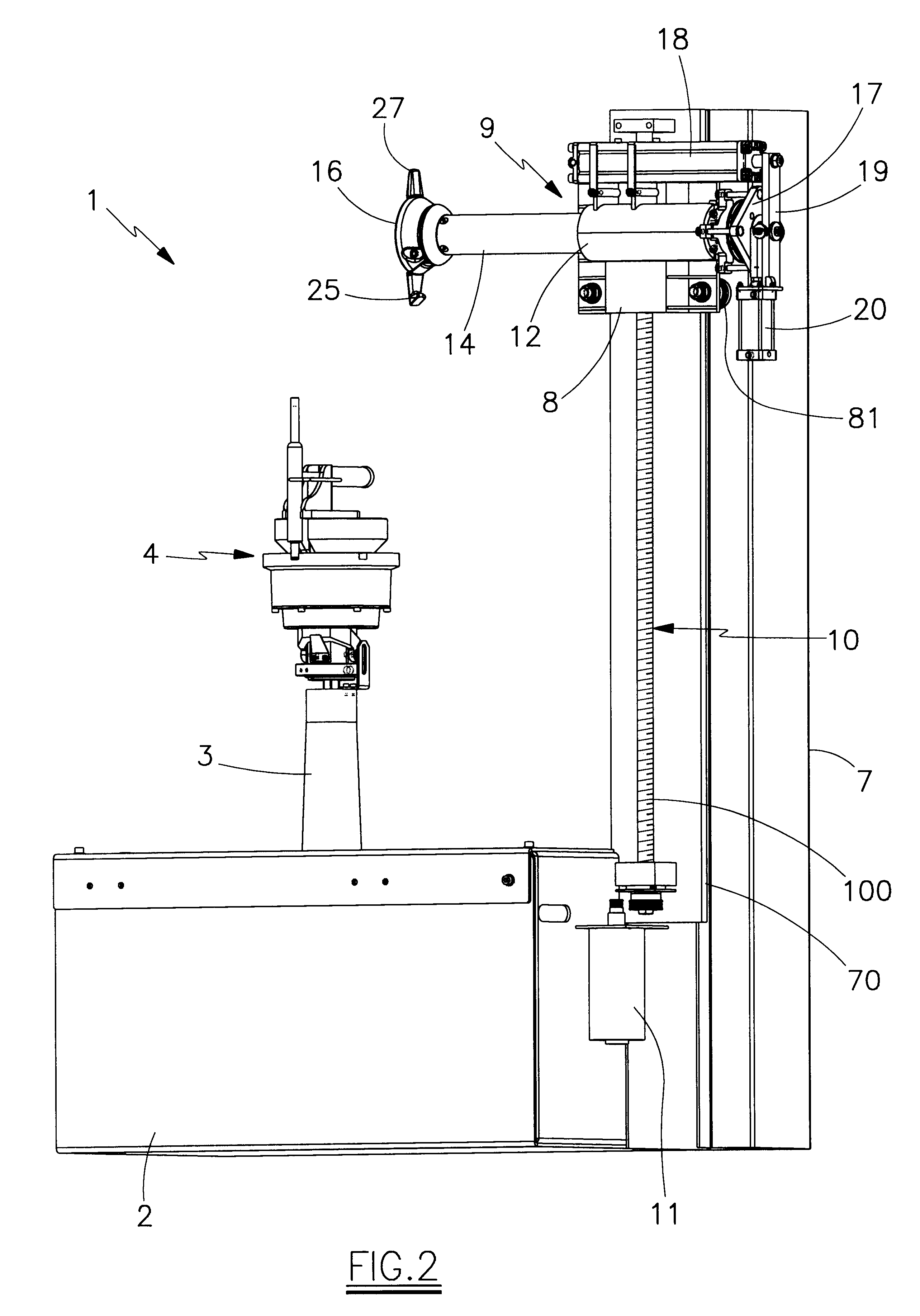
Said figures show the tyre removal machine 1, which comprises a lower base 2, from the upper surface of which there projects a rotary shaft 3 for supporting the support and a locking means 4 for the wheel rim 5 on which the tyre 6 is installed.

The shaft 3, and hence also the support and locking means 4 for the wheel rim 5, can translate radially, operated by means, known per se and not shown, positioned inside the casing 2.

It should be noted that said means 4 are not described in detail as they form the subject of the U.S. Pat. No. 6,516,855 in the name of the same Applicant.

To the rear of the casing 2 there is present a vertical frame 7 provided with guides 70 for the sliding of an automatic device 9 for mounting and removing the tyre 6 on / from the wheel rim 5.

In greater detail, the device 9 comprises a carriage 8 provided with four wheels 81 arranged to run on guides 70 of the vertical frame 71; the carriage 8 supports the means, described hereinafter, for mounting and removing th...


PUM


Abstract

An automatic device for mounting and removing a tire (6) onto and from the relative wheel rim (5), comprising, for supporting the wheel rim (5) complete with tire (6), rotary means associated with a frame (7) which supports an operating head (16), positionable in level and horizontally translatable, provided with at least one demounting tool (25) which can rotate about an axis perpendicular to the main axis of said operating head (16) to be positioned between a first position for seeking and gripping the bead of the tire (6), in which the tool (25) is orientated towards the center of the wheel rim, and a second position for extracting said bead of the tire (6) from the wheel rim, in which the tool (25) is perpendicular to the axis or is orientated in the opposite direction.

Description

1. Technical Field of the InventionThis invention concerns in general those means, installed on tyre removal machines, which enable the tyre to be removed from and / or mounted on the wheel rim. The wheel rim comprises two lateral bead retaining flanges onto which the beads of the tire rest.2. Prior ArtTo mount tyres on their wheel rims, and to effect the opposite operation, machines are known comprising essentially a rotary platform of vertical axis provided with a self-centering device for locking the wheel rim, which is overlaid by a support which supports, adjustable in height and in the horizontal direction, a tool arranged to interact with the tyre edge or bead, to urge it below, or extract it from, the flange of the wheel rim.In known machines said tool is positioned at the end of a vertical support bar which slides within the end seat of a horizontal arm, to which it can be locked in level.The horizontal arm itself slides in the end seat of a vertical plate which extends upwar...

Claims


Application Information

Patent Timeline
Patent Type & Authority Patents(United States)
IPC IPC(8): B60C25/138B60C25/00B60C25/14
CPCB60C25/138B60C25/0578B60C25/0593
Inventor CORGHI, REMO
Owner NEXION SPA
Why Eureka
Try Eureka