Device for inserting fill material particles into body cavities

a technology of filling material and device, which is applied in the field of medical instruments, can solve the problems of material not providing ideal filling, granular material such as ceramic granules, tending to jam within the injection tube, spherical granules are known to jam and break apart,

Inactive Publication Date: 2003-09-16
SPINEOLOGY
View PDF13 Cites 123 Cited by
  • Summary
  • Abstract
  • Description
  • Claims
  • Application Information

AI Technical Summary

Benefits of technology

As indicated above, one application of the invention is in the field of spinal surgery. Surgeons often attempt to fill certain spaces within the spine with bone or bone substitute materials, such as bioceramic material. The filled spaces then provide mechanical support and the proper milieu for bone ingrowth. The local spinal anatomy restricts safe access to certain internal spinal areas. Therefore, surgeons are often required to operate through very small entry portals. The present invention provides the surgeon with a reliable and effective device suitable for filling cavities deep within the spine, e.g. the interbody or intra-vertebral spaces.
As shall be made clear from the description below, in at least one embodiment of the invention, the present device may be inserted through very small diameter tubes. As a result, it is possible to fill the intervertebral space with little or no retraction of sensitive local nerves and vessels. For example, this invention allows the surgeon to fill the interbody space through a portal substantially smaller than currently required for many procedures.
Another area where the present invention may be of use would be in procedures known as vertebra-plasties or kypho-plasties, wherein the surgeon attempts to fill the area occupied by a so-called "compression fracture" of the vertebral body. The present invention could be used to fill this area through the narrow confines of the vertebral pedicle or through a small (about 3-10 mm) hole in the side or front of the vertebral body. As a result, use of the invention would reasonably reduce risk and complications compared to other procedures that require a larger exposure, as in the case of the placement of large bioceramic blocks.

Problems solved by technology

Manual filling such as by insertion by hand of one or more chunks of fill material may not provide for ideal filling and compaction characteristics which may be essential to encouraging proper bone growth and fusion.
In use however, granular material such as ceramic granules tend to jam within injection tubes and tend to break apart and pulverize when injection and / or impaction forces are vigorously applied.
However, even spherical granules are known to jam and break apart during the injection procedure.
The local spinal anatomy restricts safe access to certain internal spinal areas.

Method used


Image

  • Device for inserting fill material particles into body cavities
  • Device for inserting fill material particles into body cavities
  • Device for inserting fill material particles into body cavities

Examples


Embodiment Construction

is hereafter described with specific reference being made to the drawings in which:

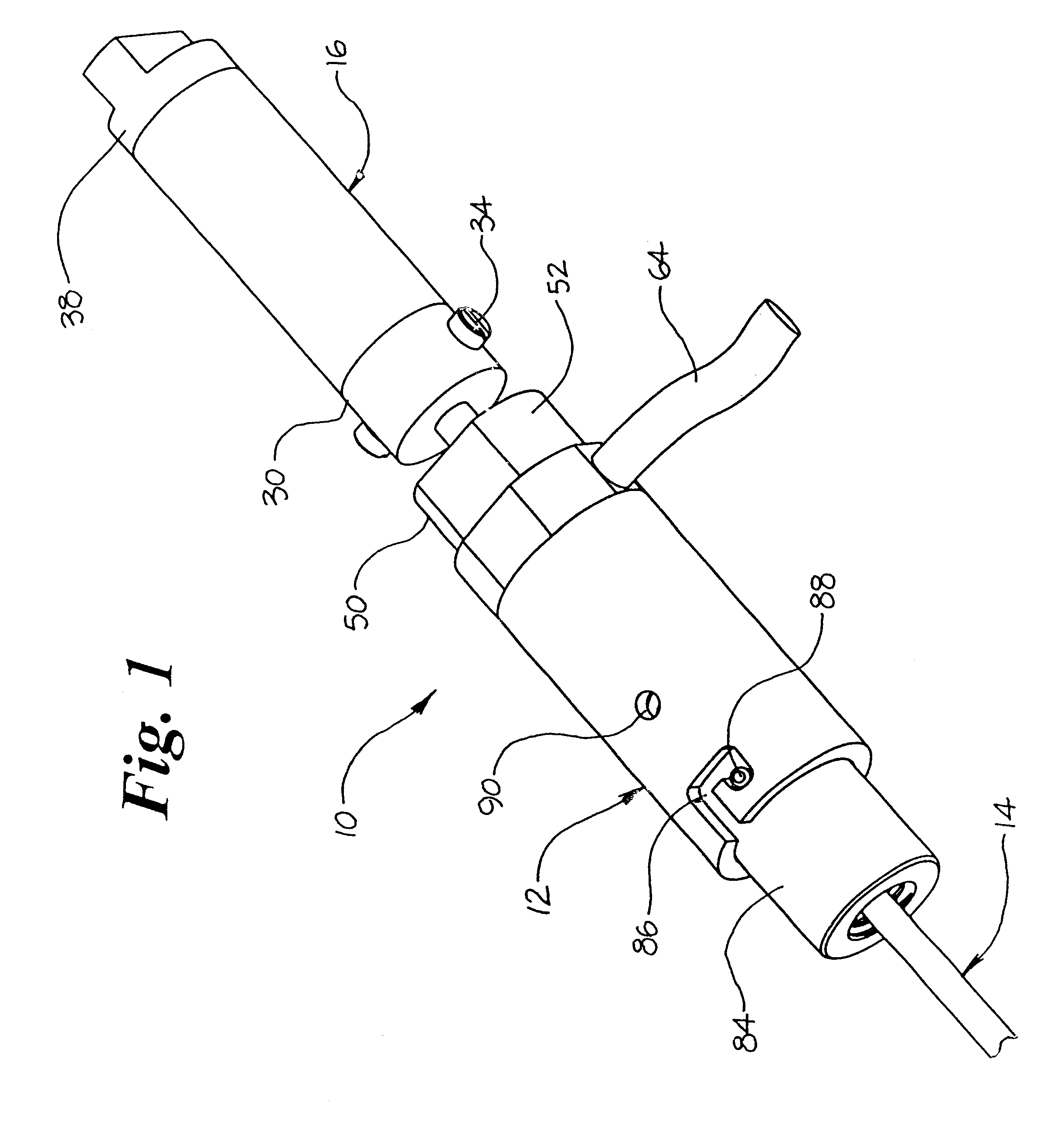
FIG. 1 is a perspective view of an embodiment of the invention;

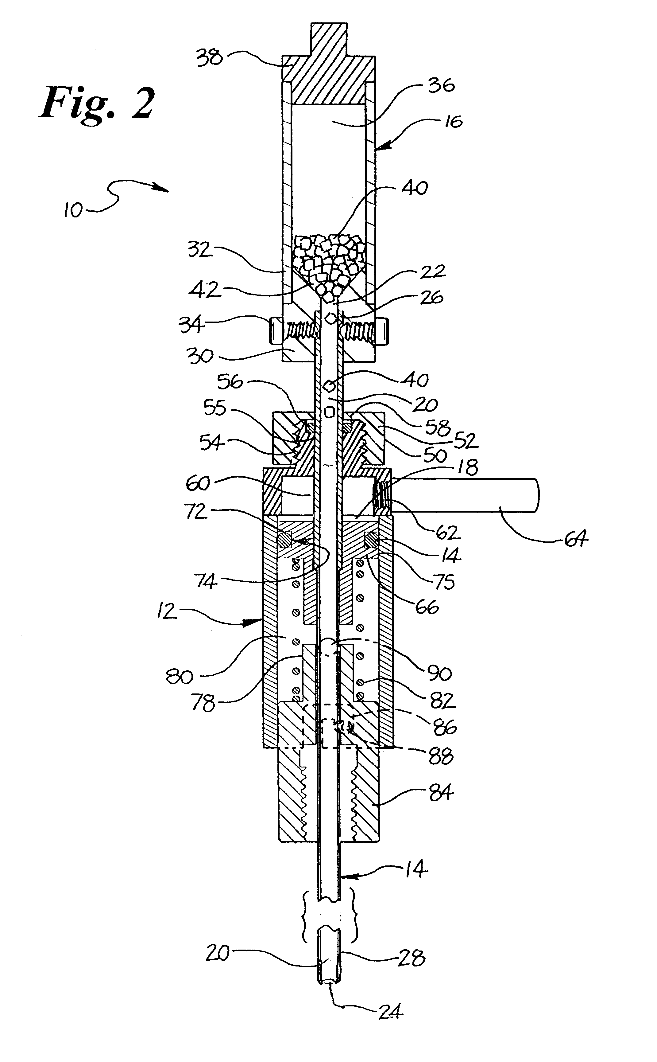
FIG. 2 is a longitudinal sectional view of the embodiment of the invention shown in FIG. 1;

FIG. 3 is an enlarged view of the angled opening slot joining the reservoir and the injection cylinder of the embodiment of the invention shown in FIG. 1;

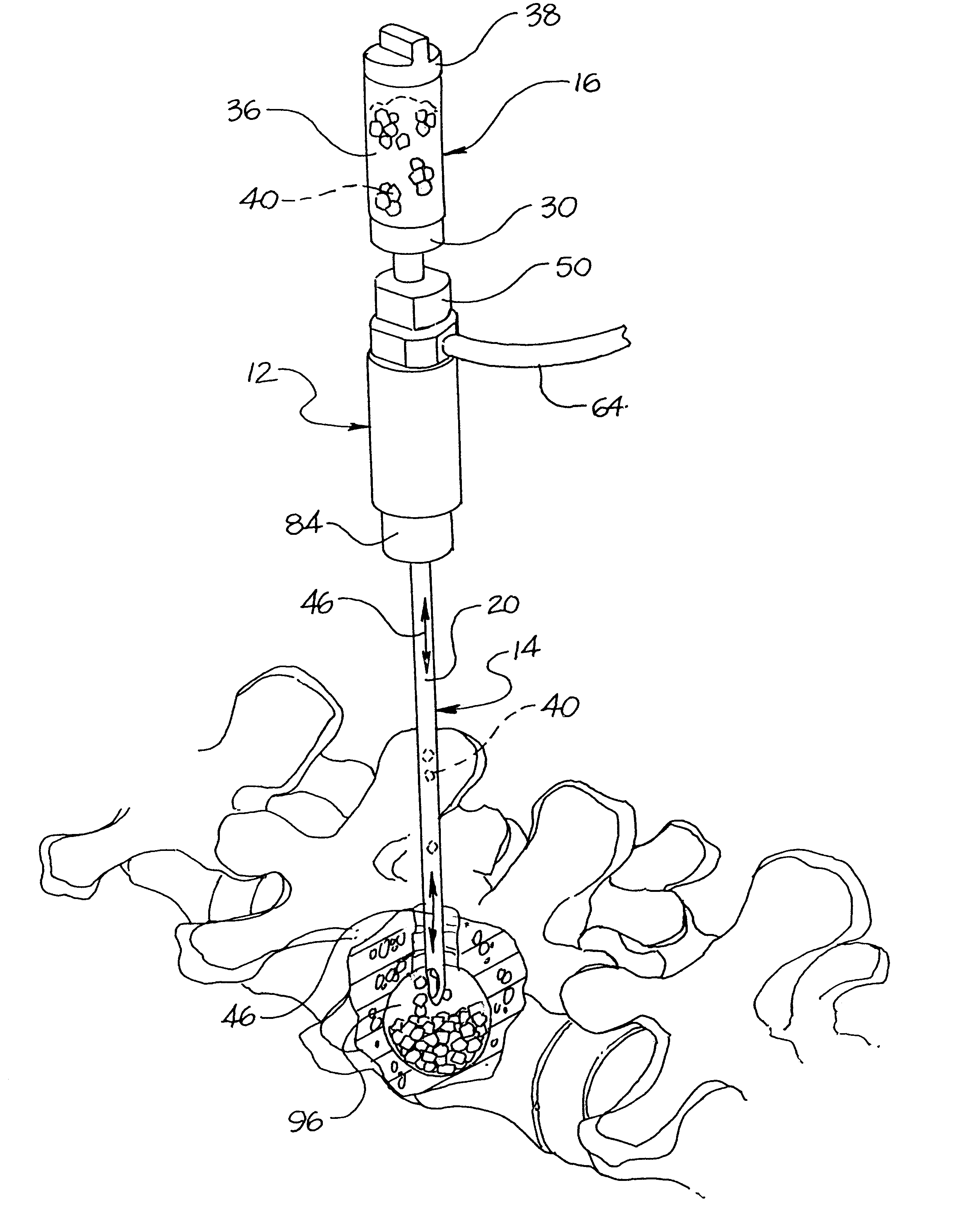
FIG. 4 is a perspective view of an embodiment of the invention as shown in its intended environment of use;

FIG. 5 is a perspective view of an embodiment of the invention as shown in its intended environment of use;

FIG. 6 is an exploded view of an embodiment of the invention;

FIG. 7 is a detailed sectional view of portions of the housing of an embodiment of the invention; and

FIG. 8 is a block diagram illustrating the use of an embodiment of the invention.

With reference to the FIGS. 1-8 wherein identical elements are numbered identically throughout, an embodiment of the inventive filler instrument, ind...


PUM


Abstract

An instrument for filling cavities in a body, such as a cavity within a reamed out spinal disc, with beads includes a cyclical agitator that functions to prompt the introduction of one bead at a time through the fill tube to prevent clogging and to promote compaction within the cavity.

Description

Not Applicable1. Field of the InventionThis invention relates to a medical instrument for filling a cavity formed within bone, a spinal disk, or a fixation device inserted therein, with biocompatible beads. More specifically, the present invention is directed to a vibratory tool having a reservoir of biocompatible material in fluid communication with a proximal end of a tubular injection cylinder, the injection cylinder and reservoir are vibrated to cause the material to pass from the reservoir into the proximal end of the injection cylinder. The vibratory action of the device and gravity allow the material to pass through the injection cylinder to its distal end and be deposited into a delivery site. The vibratory action of the injection cylinder causes the distal end of the cylinder to gently tap the deposited material thereby compacting the material within the delivery site. The unique construction and vibratory action of the present device prevents fill material from plugging th...

Claims


Application Information

Patent Timeline
Patent Type & Authority Patents(United States)
IPC IPC(8): A61B17/88A61B17/34A61B19/00A61F2/28A61F2/44A61F2/46A61B17/00
CPCA61B17/7095A61B17/00234A61B17/3468A61B17/3472A61B2019/462A61F2/28A61F2/442A61F2/4601A61F2/4611A61F2002/2835A61F2002/4602A61F2002/4635A61B2090/062
Inventor KUSLICH, STEPHEN D.PETERSON, FRANCISGLEASON, JOSEPH E.
Owner SPINEOLOGY
Why Eureka
Try Eureka