High-precision measuring method and apparatus

a measuring method and high-precision technology, applied in the direction of instruments, specific gravity measurement, heat measurement, etc., can solve the problems of high cost of equipment, high accuracy, and high cost of known techniques, and achieve the effect of low cost equipment and high degree of precision

Inactive Publication Date: 2003-09-16
NEXENSE
View PDF5 Cites 199 Cited by
  • Summary
  • Abstract
  • Description
  • Claims
  • Application Information

AI Technical Summary

Benefits of technology

An object of the present invention is to provide a method and apparatus for measuring distances, temperatures, and a number of other parameters, in a manner which can be implemented with relatively low-cost equipment and with a very high degree of precision.

Problems solved by technology

Many measuring techniques are known for measuring distance, temperature, and other parameters, but such known techniques generally increase in expense according to the precision desired, and also generally have an upper limit as to the precision practically attainable by the technique.
For example, to measure distances of meters or kilometers with a precision of microns or fractions of microns is extremely expensive, if attainable at all.
The same limitations apply with respect to measuring temperature and other conditions.

Method used


Image

  • High-precision measuring method and apparatus
  • High-precision measuring method and apparatus
  • High-precision measuring method and apparatus

Examples


Embodiment Construction

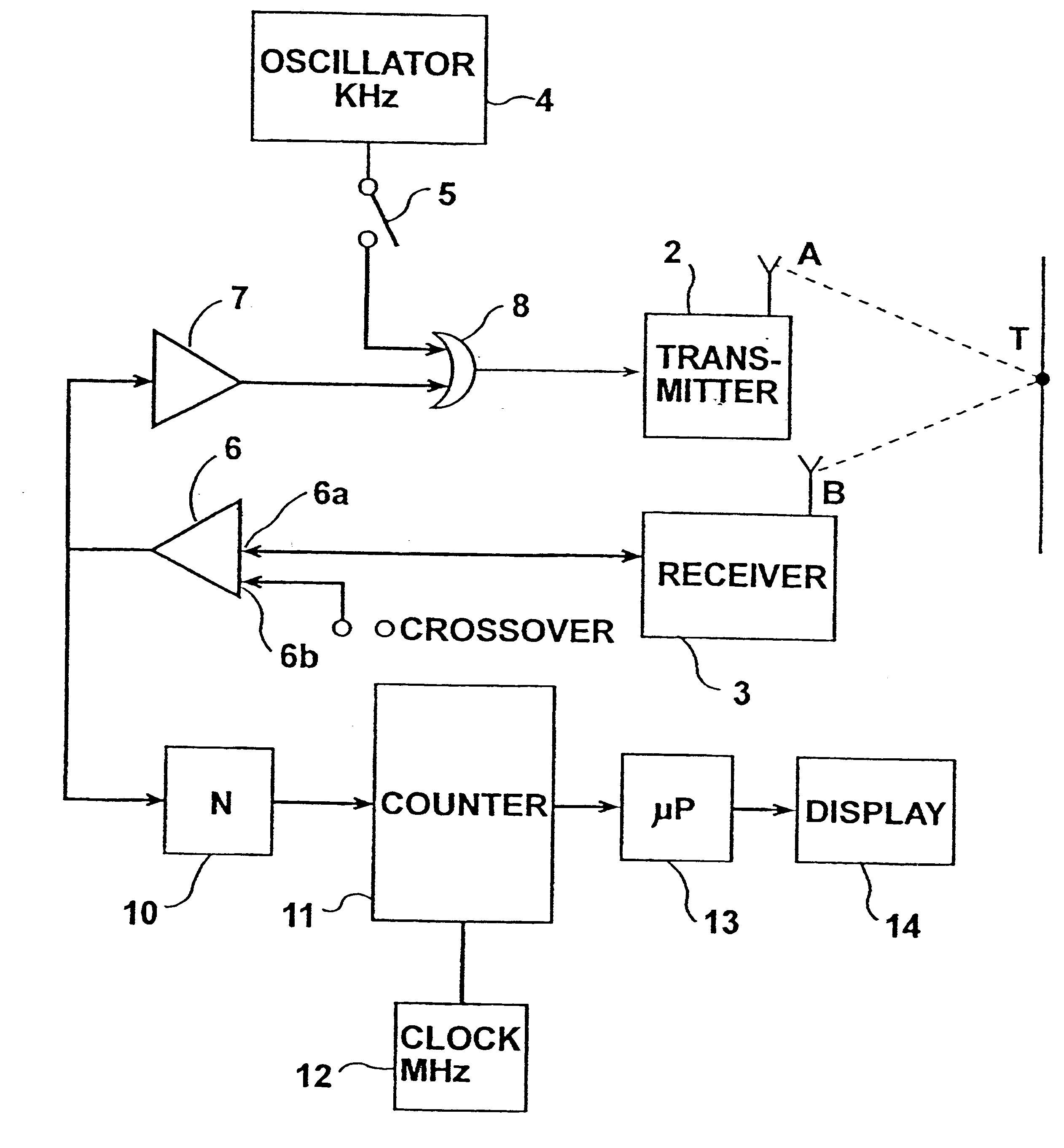
FIG. 1 is a block diagram illustrating a system for precisely measuring the distance to point T of a target or other object. The illustrated system is an echo system, and therefore the distance to target T is measured by measuring the transmit time taken by a cyclically-repeating energy wave transmitted at point A towards the target T until its echo is received at point B.

The system illustrated in FIG. 1 thus includes a transmitter 2 at location A for transmitting the cyclically-repeating energy wave towards target T, and a receiver 3 at location B for receiving the echo of the cyclically-repeating energy wave after reflection from target T. Initially, the energy wave is continuously transmitted from an oscillator 4 under the control of a switch 5 until the echoes are received by receiver 3; once the echoes are received, switch 5 is opened so that the received echo signals are then used for controlling the frequency of transmission of the cyclically-repeating energy wave by transmit...


PUM

PropertyMeasurementUnit
wavelengthsaaaaaaaaaa
transit distance ATBaaaaaaaaaa

Abstract

A method and apparatus of measuring a predetermined parameter having a known relation to the transit time of movement of an energy wave through a medium, by transmitting from a first location in the medium a cyclically-repeating energy wave; receiving the cyclically-repeating energy wave at a second location in the medium; detecting a predetermined fiducial point in the cyclically-repeating energy wave received at the second location; continuously changing the frequency of transmission of the cyclically-repeating energy wave from the first location to the second location in accordance with the detected fiducial point of each received cyclically-repeating energy wave received at the second location such that the number of waves received at the second location from the first location is a whole integer; and utilizing the change in frequency to produce a measurement of the predetermined parameter.

Description

FIELD AND BACKGROUND OF THE INVENTIONThe present invention relates to high precision measuring methods and apparatus, and particularly to a method and apparatus for measuring distance, temperature, and any other parameter having a known relation to the transmit time of movement of an energy wave through a medium.Many measuring techniques are known for measuring distance, temperature, and other parameters, but such known techniques generally increase in expense according to the precision desired, and also generally have an upper limit as to the precision practically attainable by the technique. For example, to measure distances of meters or kilometers with a precision of microns or fractions of microns is extremely expensive, if attainable at all. The same limitations apply with respect to measuring temperature and other conditions.OBJECTS AND BRIEF SUMMARY OF THE INVENTIONAn object of the present invention is to provide a method and apparatus for measuring distances, temperatures, a...

Claims


Application Information

Patent Timeline
Patent Type & Authority Patents(United States)
IPC IPC(8): G01N29/02G01F1/66G01B21/02G01N29/024G01N29/34G01K11/00G01K11/26A61B5/08A61B5/11G01K11/22A61B8/00G01N22/00G01N29/00G01S15/08
CPCA61B5/0507G01B21/02G01F1/667G01K11/22G01K11/26G01N29/024G01N29/348G01N2291/02836G01N2291/02881G01N2291/102
Inventor ARIAV, ARIE
Owner NEXENSE
Why Eureka
Try Eureka