Multi-port fuel injection nozzle and system and method incorporating same

a fuel injection nozzle and multi-port technology, applied in the field of internal combustion engine injection systems, can solve the problems of fuel-air mixture affecting the combustion process, forming pollutants, and conventional combustion engines operating inefficiently and producing pollutants

Inactive Publication Date: 2003-09-30
BRP US
View PDF7 Cites 31 Cited by
  • Summary
  • Abstract
  • Description
  • Claims
  • Application Information

AI Technical Summary

Problems solved by technology

It is also well known that the fuel-air mixture affects the combustion process and the formation of pollutants, such as Sulfur Oxides, Nitrogen Oxides, Hydrocarbons, and particulate matter.
However, conventional combustion engines continue to operate inefficiently and produce pollutants due to poor fuel-air mixing in the combustion chamber.

Method used


Image

  • Multi-port fuel injection nozzle and system and method incorporating same
  • Multi-port fuel injection nozzle and system and method incorporating same
  • Multi-port fuel injection nozzle and system and method incorporating same

Examples


Embodiment Construction

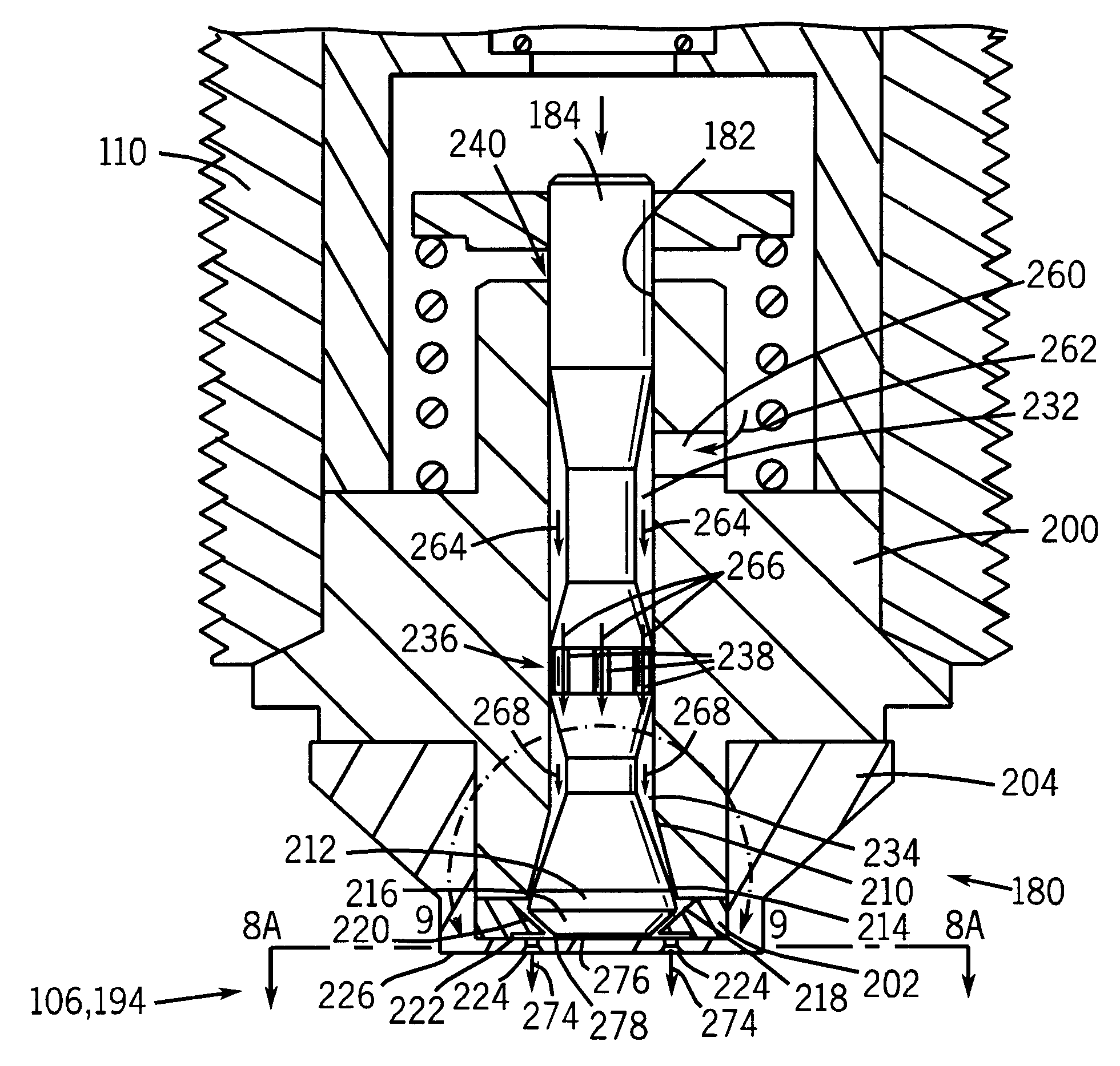
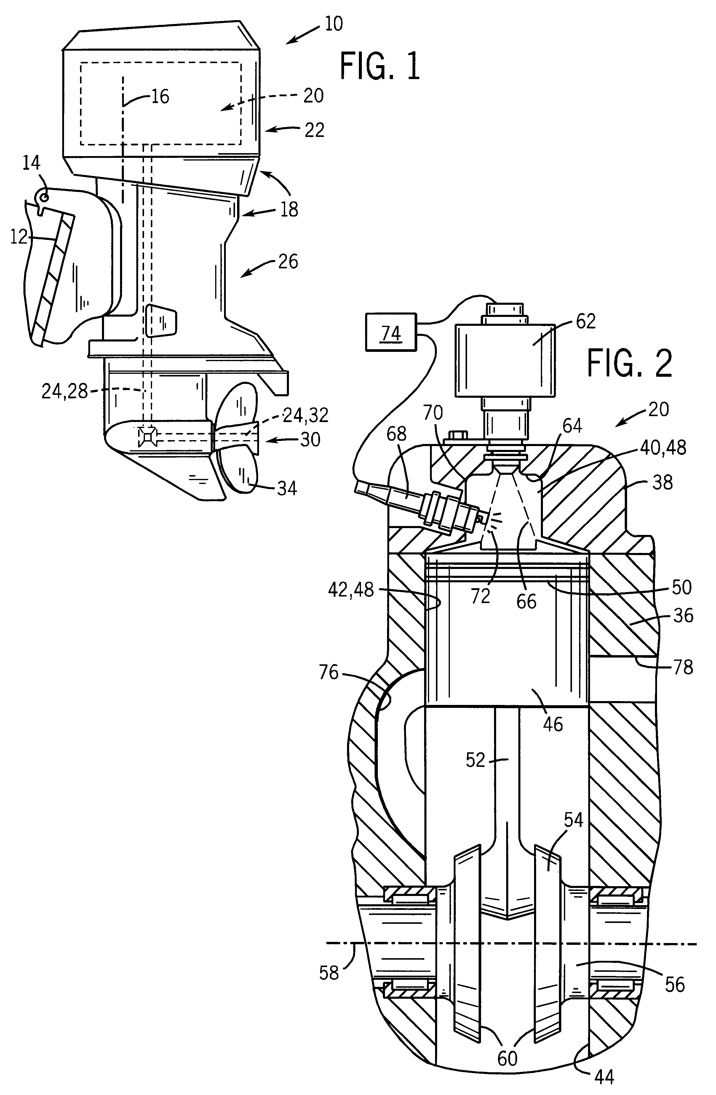
The present technique will be described with respect to a 2-cycle outboard marine engine as illustrated in FIGS. 1-2. However, it will be appreciated that this invention is equally applicable for use with a 4-cycle engine, a diesel engine, or any other type of internal combustion engine having at least one fuel injector, which may have one or more geometrically varying fluid passageways leading to a nozzle exit. The present technique is also applicable in other applications utilizing fluid spray assemblies, such as a nozzle producing a hollow or solid cone-shaped droplet spray.

FIG. 1 is a side view of a marine propulsion device embodying an outboard drive or propulsion unit 10 adapted to be mounted on a transom 12 of a watercraft for pivotal tilting movement about a generally horizontal tilt axis 14 and for pivotal steering movement about a generally upright steering axis 16. The drive or propulsion unit 10 has a housing 18, wherein a fuel-injected, two-stroke internal combustion en...


PUM


Abstract

A technique is provided for enhancing fluid flow in an outwardly opening nozzle assembly. A flow enhancement assembly is provided adjacent an exit from an outwardly opening poppet to provide desired spray characteristics. The flow enhancement assembly includes converging and diverging passages and a plurality of ports to form a spray.

Description

1. Field of the InventionThe present invention relates generally to the field of internal combustion engine injection systems. More particularly, the invention relates to a technique for controlling fluid flow and spray characteristics of a spray assembly by providing a flow enhancement assembly near the exit of an outwardly opening poppet.2. Description of the Related ArtIn fuel-injected engines, it is generally considered desirable that each injector delivers approximately the same quantity of fuel in approximately the same temporal relationship to the engine for proper operation. It is also well known that the fuel-air mixture affects the combustion process and the formation of pollutants, such as Sulfur Oxides, Nitrogen Oxides, Hydrocarbons, and particulate matter. Although combustion engines utilize a variety of mixing techniques to improve the fuel-air mixture, many combustion engines rely heavily on spray assemblies to disperse fuel throughout a combustion chamber. These spra...

Claims


Application Information

Patent Timeline
Patent Type & Authority Patents(United States)
IPC IPC(8): F02M57/02F02M61/16F02M61/08F02M57/00F02M61/00F02B75/00F02M61/18F02M63/00F02B75/22F02M63/06F02B61/00F02B61/04F02B75/02F02B23/10F02B75/18
CPCF02B61/045F02B75/22F02M57/027F02M61/08F02M61/162F02M61/1853F02M63/06F02B23/101F02B2075/025F02B2075/1816F02B2075/1824
Inventor PARRISH, SCOTT E.
Owner BRP US
Why Eureka
Try Eureka