Deinterlacing device and method

a technology of interpolation device and interpolation device, which is applied in the direction of picture reproducers using projection device, signal generator with optical-mechanical scanning, television systems, etc., can solve the problems of image quality deterioration image quality deterioration

Inactive Publication Date: 2003-10-07
LG ELECTRONICS INC
View PDF5 Cites 68 Cited by
  • Summary
  • Abstract
  • Description
  • Claims
  • Application Information

AI Technical Summary

Problems solved by technology

However, some types of displays do not process the interlacing image data but they process a progressive image data which is used on a monitor of a computer, instead.
The line repetition method is realized with a simple hardware but has a defect that a quality of image is deteriorated after interpolation.
The inter-field interpolation without motion-compensation method is realized with a simple hardware but has a defect that even if the motion image is interpolated, an error is generated or a screen is degraded, thereby causing a quality of image to be deteriorated.
However, it has a defect that after the interpolation of still image, the screen is degraded, thereby causing a quality of image to be deteriorated.
However, in case of the screen where the motion speed is relatively fast when compared with the period of each field to be interpolated, it has a defect that the interpolation is difficult or has been erroneously executed.
As described above, such the conventional methods for converting the interlacing image data into the progressive image data suffer the problem that the quality of image is poor after the interpolation or the interpolation is erroneously executed.
However, these methods suffer a problem that a manufacturing cost of a circuit is expensive due to a plurality of field memories and a relatively complicated procedure.

Method used


Image

  • Deinterlacing device and method
  • Deinterlacing device and method
  • Deinterlacing device and method

Examples


Embodiment Construction

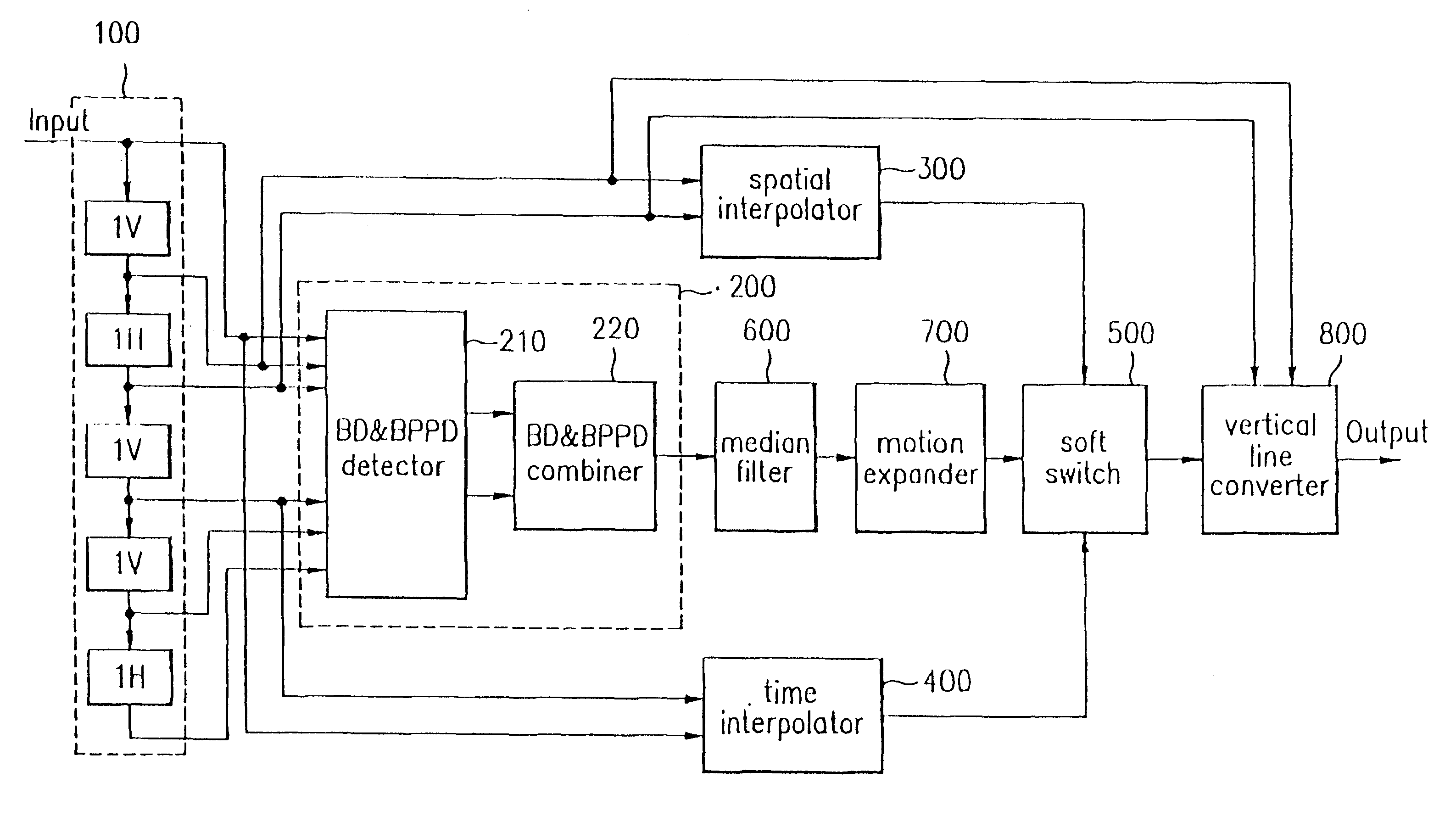
FIG. 3 is a schematic block diagram illustrating the construction of a deinterlacing device according to the present invention.

In construction, a field memory 100 stores m continuous field image data containing a current field data (i.e., an nth field data), a previous field data, a next field data and the like, on the basis of the nth field data of a plurality of field data for output image. In other words, the field memory 100 stores the nth field data and the previous and next field data to the nth field data.

A motion determination part 200 detects the picture element values and brightness profile pattern difference values in specific lines existing among the field data stored in the field memory 100 to thereby calculate a motion value of a moving picture.

The motion determination part 200 is comprised of a brightness difference and brightness profile pattern difference (hereinafter, which is referred simply to BD and BPPD) detector 210 for calculating the brightness difference an...


PUM


Abstract

A deinterlacing device and method for improving a quality of image after interpolation without a complicated circuit at the time when an interlacing screen is converted into a progressive type screen is disclosed. The deinterlacing device includes: a field memory for storing m continuous field data containing an nth field data and positioned before and after the nth field data on the basis of the nth field data of a plurality of field data for output image; a motion determination part for detecting picture element values and brightness profile pattern difference values in specific lines existing among the field data stored in the field memory to calculate a motion value of a moving picture; a spatial interpolator for calculating a variation direction of picture element values on an area to be interpolated in the nth field data to output a direction value; a time interpolator for averaging the picture element values on the area to be interpolated in a previous field data of the nth field data and the picture element values on the area to be interpolated in a next field data of the nth field data to output the picture element average value; and a soft switch for mixing the direction value outputted from the spatial interpolator and the picture element average value outputted from the time interpolator, based upon the motion value determined in the motion determination part to output the mixed result.

Description

1. Field of the InventionThe present invention relates to an image processing method, and more particularly, to a deinterlacing device and method capable of converting interlace field image data into a progressive frame image data.2. Discussion of Related ArtInterlacing image data is displayed on one frame of screen composed of two fields, i.e., an odd field and an even field, as shown in FIG. 1.However, some types of displays do not process the interlacing image data but they process a progressive image data which is used on a monitor of a computer, instead. In this case, there is a need to install an additional system for converting the interlacing image data into the progressive image data in the interior of the display.A method for converting the interlacing image data into the progressive image data is embodied in various ways, as shown in FIGS. 2a to 2c.As to a line repetition method, as shown in FIG. 2a, one frame is made in such a manner that the line information of a curren...

Claims


Application Information

Patent Timeline
Patent Type & Authority Patents(United States)
IPC IPC(8): H04N5/44H04N5/14
CPCH04N7/012H04N5/144
Inventor SHIN, CHANG YONGHAN, DONG IL
Owner LG ELECTRONICS INC
Why Eureka
Try Eureka