Vertical fencing

a vertical tube and fencing technology, applied in the field of vertical tube fencing, can solve the problems of difficult and expensive transportation from the manufacturing location to the fence site, the difficulty of crimping the inability to reliably crimp the tubes used for vertical tube fencing,

Inactive Publication Date: 2003-10-14
WALMSLEY ROGER
View PDF12 Cites 48 Cited by
  • Summary
  • Abstract
  • Description
  • Claims
  • Application Information

AI Technical Summary

Problems solved by technology

A fencing section would comprise two rails and perhaps twenty bars, and clearly such fencing sections were extremely heavy and so difficult and expensive to transport from the manufacturing location to the fence site.
However, it has not been found possible reliably to crimp the tubes used for vertical tube fencing, so that the "Nibal" system is not practical for self-adjusting vertical tube fencing.
Notwithstanding that the "Nibal" system is not practical for vertical tube fencing, architects, customers, and the like are still demanding self-adjustment, so that there is a requirement for an alternative to the "Nibal" system which is suitable for vertical tube fencing.
Preferably, when the projection is engaged in the recess means movement of the fence member parallel to its longitudinal axis is limited.
Preferably also, when the projection is engaged in the recess means rotational movement of the fence member about its longitudinal axis is limited.

Method used


Image

  • Vertical fencing
  • Vertical fencing
  • Vertical fencing

Examples


Embodiment Construction

In the following description, directional and orientational terms such as "top", "bottom" etc. refer to the orientation of the components as drawn, which will typically also be the orientation of use.

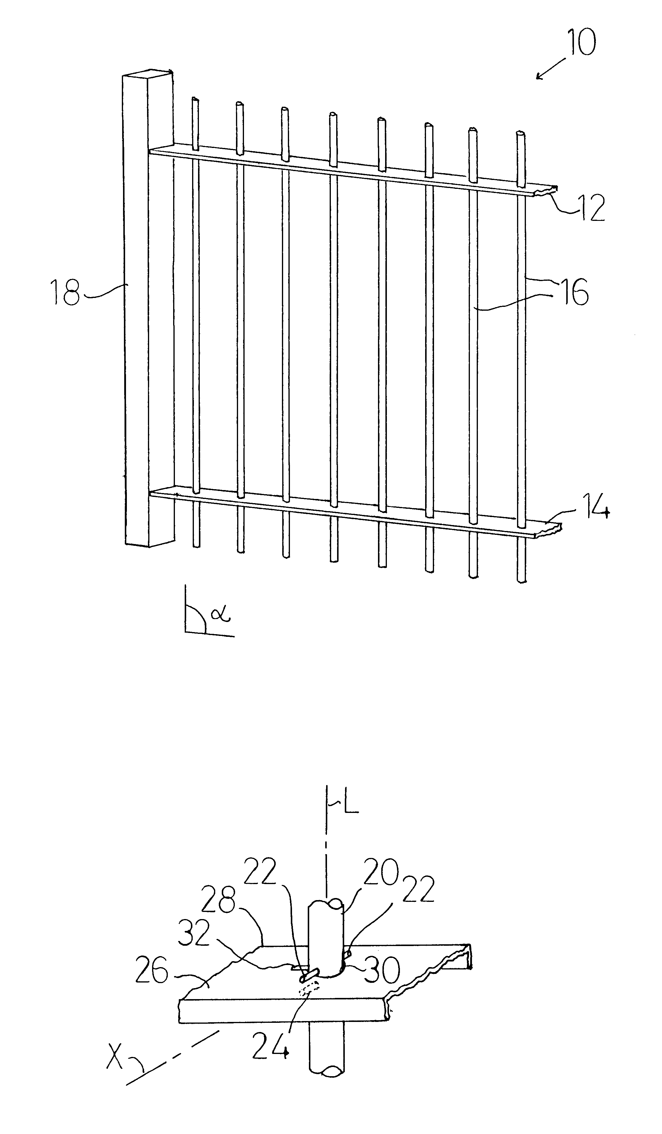
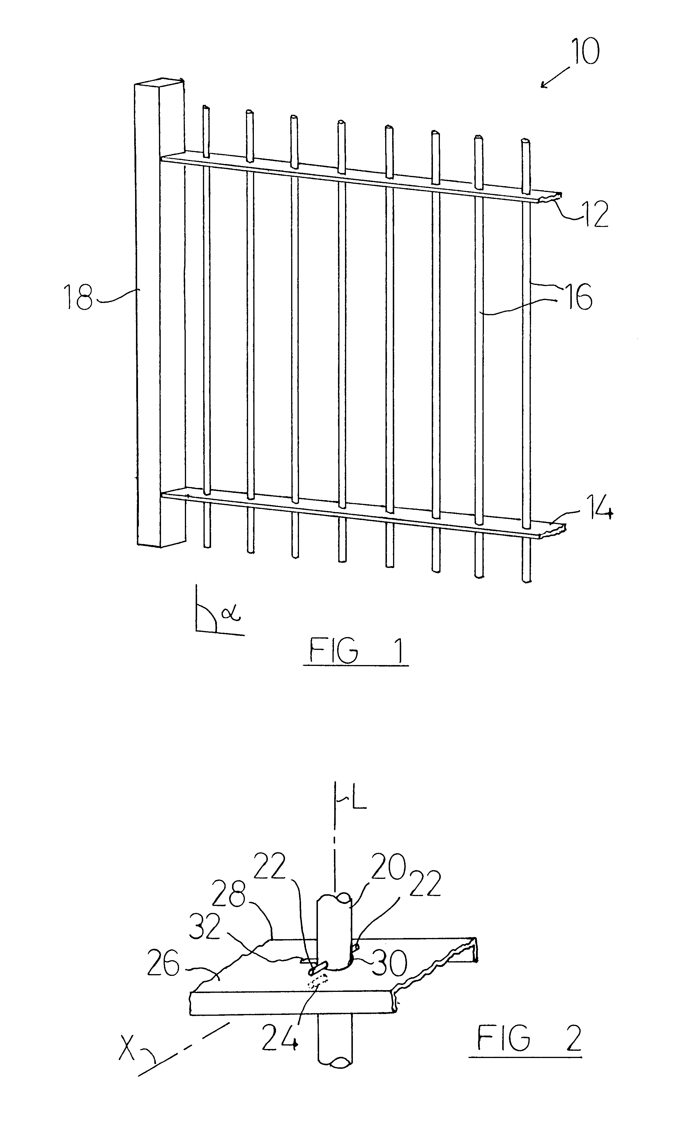
The vertical fence section 10 (part of which is shown in FIG. 1) comprises two rails 12,14 to which a number of fence members 16 are attached. The rails 12,14 are both connected to a post 18 in known fashion. In this embodiment, the fence is non-self-adjusting, so that the angular (in this embodiment perpendicular) relationship between the fence members 16 and the rails 12,14 is fixed. The fence members 16 in this embodiment are welded to the rails 12,14.

Typically, an assembed fence will comprise a number of fence sections 10, each fence section being connected to posts 18 by way of the ends of the rails 12,14. The posts 18 define the line of the fence and are erected on the site. The fence sections 10 are generally pre-assembled i.e. manufactured off-site and supplied to the site ready...


PUM


Abstract

In self-adjusting vertical tube fencing, a rail and a method of assembling the fencing are provided. The rail comprises an elongated channel with a top wall and two side walls, each of the side walls being of substantial U-section with an outer part connected to the top wall and an inner inturned part, the top wall having a series of apertures through which respective tubular fence members are fitted. The inturned parts have a notch which can accommodate a fixed peg carried by a fence member. The inturned parts also have an extension adjacent the notch, the extension being provided to permit rotation of the fence member about its longitudinal axis during assembly so that the peg can engage the notch.</PTEXT>

Description

This invention relates to vertical fencing, and in particular to vertical tube fencing.BACKGROUND TO THE INVENTIONVertical fencing has been known for a number of years. This fencing comprises (in use) a plurality of vertical fence members which are supported by two substantially horizontal rails, a rail being located adjacent the top and bottom of the fence members. The fencing is adapted as security fencing to prevent access by unauthorised persons, and so the fence members are sufficiently closely spaced to prevent such access. Typically the fence members are of a length to prevent or reduce the likelihood that the fence can be climbed, and the rails are positioned sufficiently far apart to impair their use as a climbing aid for a person wishing to climb over the fence. In addition, the fence members project beyond the top rail, and their free ends can carry spikes or other features (which may be partly decorative), which spikes or features act to dissuade a person from climbing o...

Claims


Application Information

Patent Timeline
Patent Type & Authority Patents(United States)
IPC IPC(8): E04H17/14
CPCE04H17/1439
Inventor WALMSLEY, ROGER
Owner WALMSLEY ROGER
Why Eureka
Try Eureka