Labeling machine

a labeling machine and labeling head technology, applied in the field of labeling machines, can solve the problems of affecting the positioning of labels relative to articles, complicating the control of the pivoting of the labeling head, etc., and achieve the effect of reducing the inertia moment and compact structur

Inactive Publication Date: 2003-10-21
NS TESTUT
View PDF10 Cites 22 Cited by
  • Summary
  • Abstract
  • Description
  • Claims
  • Application Information

AI Technical Summary

Benefits of technology

Placing the active print means on board the labeling head, avoids incessant go-and-return trips of the labeling head between external print means and a labeling position overlying the conveyor of the labeling machine.
Advantageously, the active print means are controlled by control means that are not secured to the labeling head. The portions of the printer that are not active from the point of view of printing are thus located on the labeling machine, thereby simplifying the design of the labeling head.
By "twisted", it should be understood that the midplane of the strip does not remain constant as the strip travels between the roll and the active print means. The roll is thus offset from the active print means, thus making it possible to design a labeling head that presents a smaller moment of inertia, and that is of more compact structure.
In a first embodiment, the roll is placed on the labeling head beside the active print means. The roll is thus placed close to the axis of rotation of the labeling head, thereby reducing its moment of inertia.
In a second embodiment, the roll is mounted to rotate on the structure of the labeling machine, with the deflector members comprising a deflector cylinder secured to the labeling head and extending parallel to the pivot axis of the labeling head. In this way, the labeling head is lightened by a weight corresponding to the weight of the roll, and because of the deflection parallel to its pivot axis, the labeling head can still be oriented at any angle while nevertheless ensuring that the support strip is fed properly.

Problems solved by technology

These correcting displacements make it awkward to position a label relative to an article.
Furthermore, these displacements vary with varying angle of rotation for the labeling head, further complicating control of pivoting of the labeling head.

Method used


Image

  • Labeling machine
  • Labeling machine
  • Labeling machine

Examples


Embodiment Construction

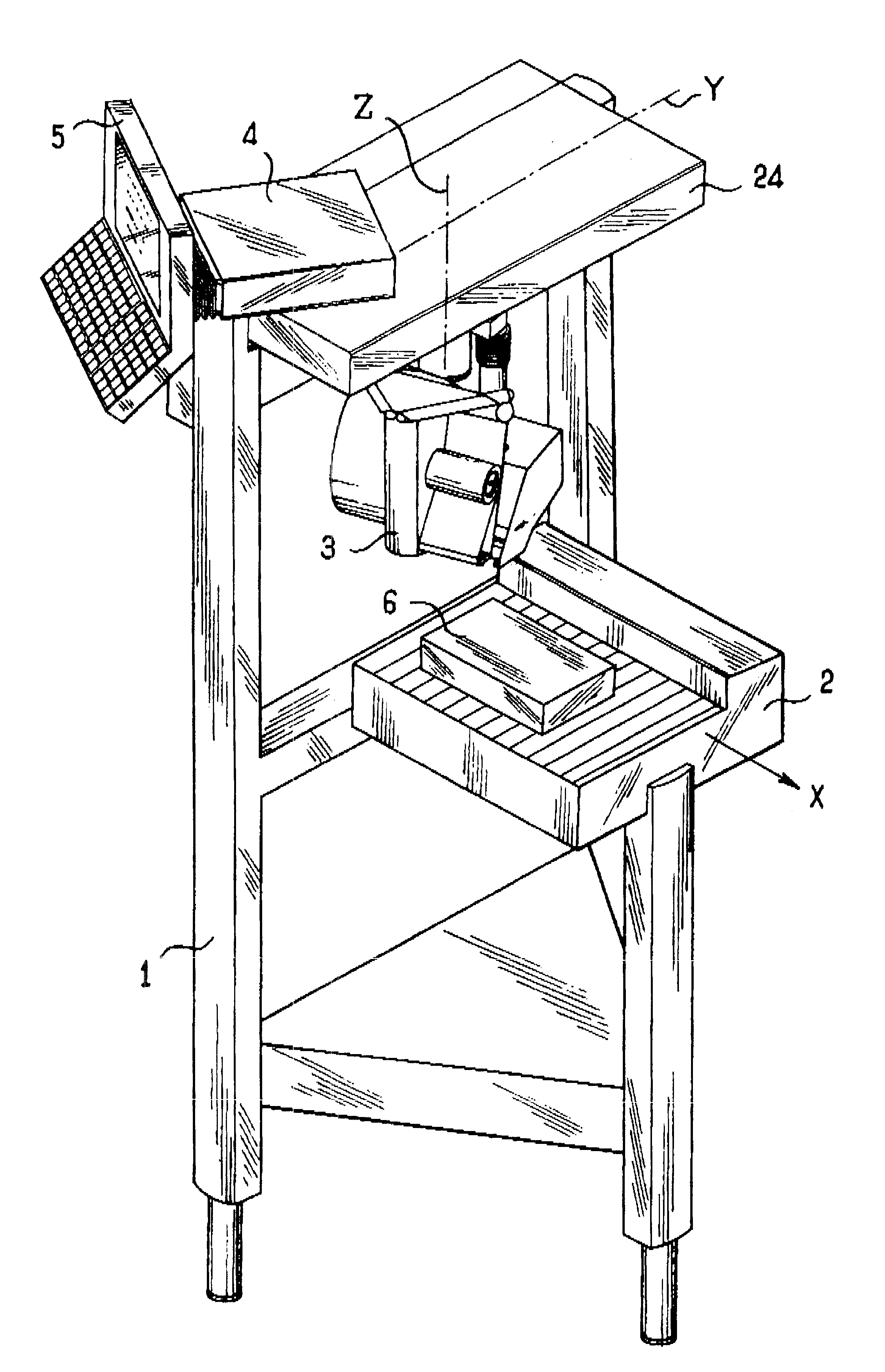
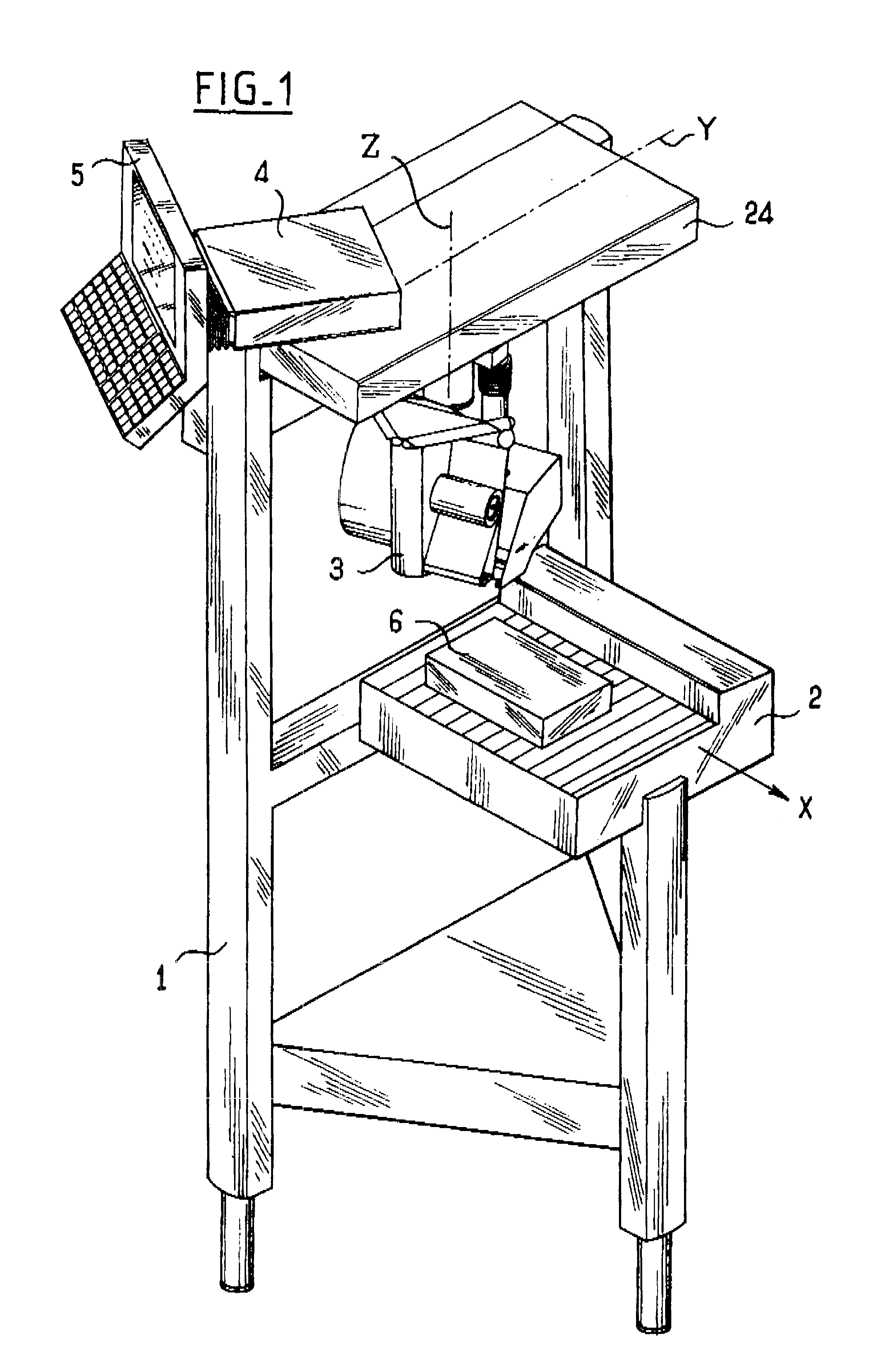
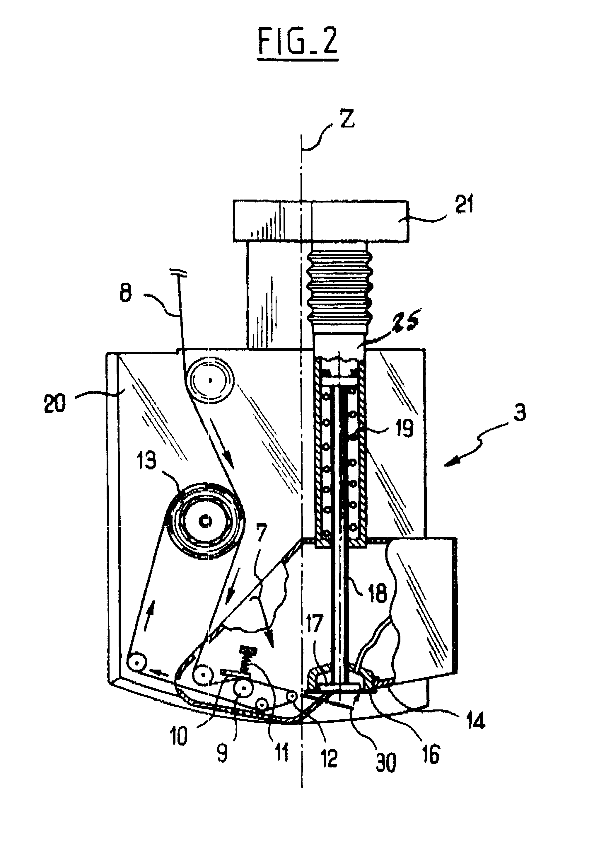
With reference to FIG. 1, a labeling machine comprises a structure 1 carrying a conveyor 2, in this case of the roller type, together with a labeling head 3 which is described below with reference to FIG. 2.

The labeling head 3 is mounted to move on a bracket or gantry 24 of the structure 1 which extends over the conveyor 2 transversely to a forward travel direction X thereof. The head is movable along the bracket 24 in a direction Y that is substantially perpendicular to the forward travel direction X of the conveyor 2. The labeling head 3 is also suitable for pivoting relative to the bracket 24 about an axis of rotation Z that is perpendicular to the direction X and Y.

Displacements along the directions X and Y enable the labeling head 3 to be put into a determined position over an article to be labeled 6, while pivoting about the axis Z enables the orientation of the labeling head 3 to be adjusted relative to the article 6.

The structure 1 also carries a unit 4 containing the contro...


PUM

PropertyMeasurementUnit
angleaaaaaaaaaa
axis of rotationaaaaaaaaaa
displacementsaaaaaaaaaa

Abstract

The invention provides a labeling machine comprising a structure, a labeling head capable of pivoting relative to the structure about a pivot axis, the labeling head being fitted with gripper means for gripping a label holding it in a plane that is substantially normal to the pivot axis of the labeling head, and placing means carried by the labeling head and adapted to take the label held by the gripper means and place it on an article to be labeled that is present on the labeling machine. According to the invention, the gripper means hold a label in such a manner that a corner thereof coincides substantially with the point of intersection of the pivot axis and the plane of the label.

Description

The invention relates to a labeling machine.As a general rule, a conventional labeling machine comprises a conveyor for transporting articles to be labeled and a labeling head mounted on a bracket extending over the conveyor and fitted with label-gripper means that hold the label in a plane parallel to the face of an article in register with the labeling head. Applicator means secured to the labeling head are adapted to move the label held by the gripper means onto the article that is to be labeled. The labeling head moves on the bracket in a direction perpendicular to the travel direction of the conveyor.In order to adjust the position of the label on the article, the movement of the labeling machine head on the bracket is controlled as is the advance of the conveyor in such a manner as to cause a reference point on the labeling machine head to coincide with a reference point on the article, in general the corner of a label-receiving zone on the article.The labeling machine is some...

Claims


Application Information

Patent Timeline
Patent Type & Authority Patents(United States)
IPC IPC(8): B65C1/00B65C1/02B65C9/08B65C9/46B65C9/18
CPCB65C1/021B65C9/1826B65C9/1884B65C9/46Y10T156/171Y10T156/1744Y10T156/1707Y10T156/1776
Inventor BARBOSA, VALDEMAR
Owner NS TESTUT
Why Eureka
Try Eureka