CDMA radio communication system using chip interleaving

a radio communication system and radio communication technology, applied in the field of cdma radio communication system, can solve the problems of limited system capacity, low quality, and low cell radius, and achieve the effects of reducing overhead, reducing transmission power control, and keeping the quality of each symbol in a frame constan

Inactive Publication Date: 2003-10-21
INVT SPE LLC
View PDF10 Cites 33 Cited by
  • Summary
  • Abstract
  • Description
  • Claims
  • Application Information

AI Technical Summary

Benefits of technology

Considering of the aforementioned point, the present inventors found out the interleaving of spread chips enables a quality of each symbol in a frame to be kept constant, while a rate of transmission power control to be alleviated, and achieved the present invention. It is thereby possible to reduce overhead and decrease interference amounts to other cells.

Problems solved by technology

However, in the conventional CDMA radio communication system, since spread signals are arranged to be concentrated upon a successive short time in the same frequency, when the short time is affected by fading and shadowing, qualities of all chips in the time deteriorate at the same time, resulting in that the qualities are not improved even though the spreading gain is obtained by despreading.
It thereby results in another problem that the system capacity is limited because the transmission is performed under large transmission power.
Therefore, a guard time corresponding to a propagation delay time is required with the length limited to ensure the transmission efficiency, thereby resulting in the problem that a cell radius is limited.

Method used


Image

  • CDMA radio communication system using chip interleaving
  • CDMA radio communication system using chip interleaving
  • CDMA radio communication system using chip interleaving

Examples


embodiment 1

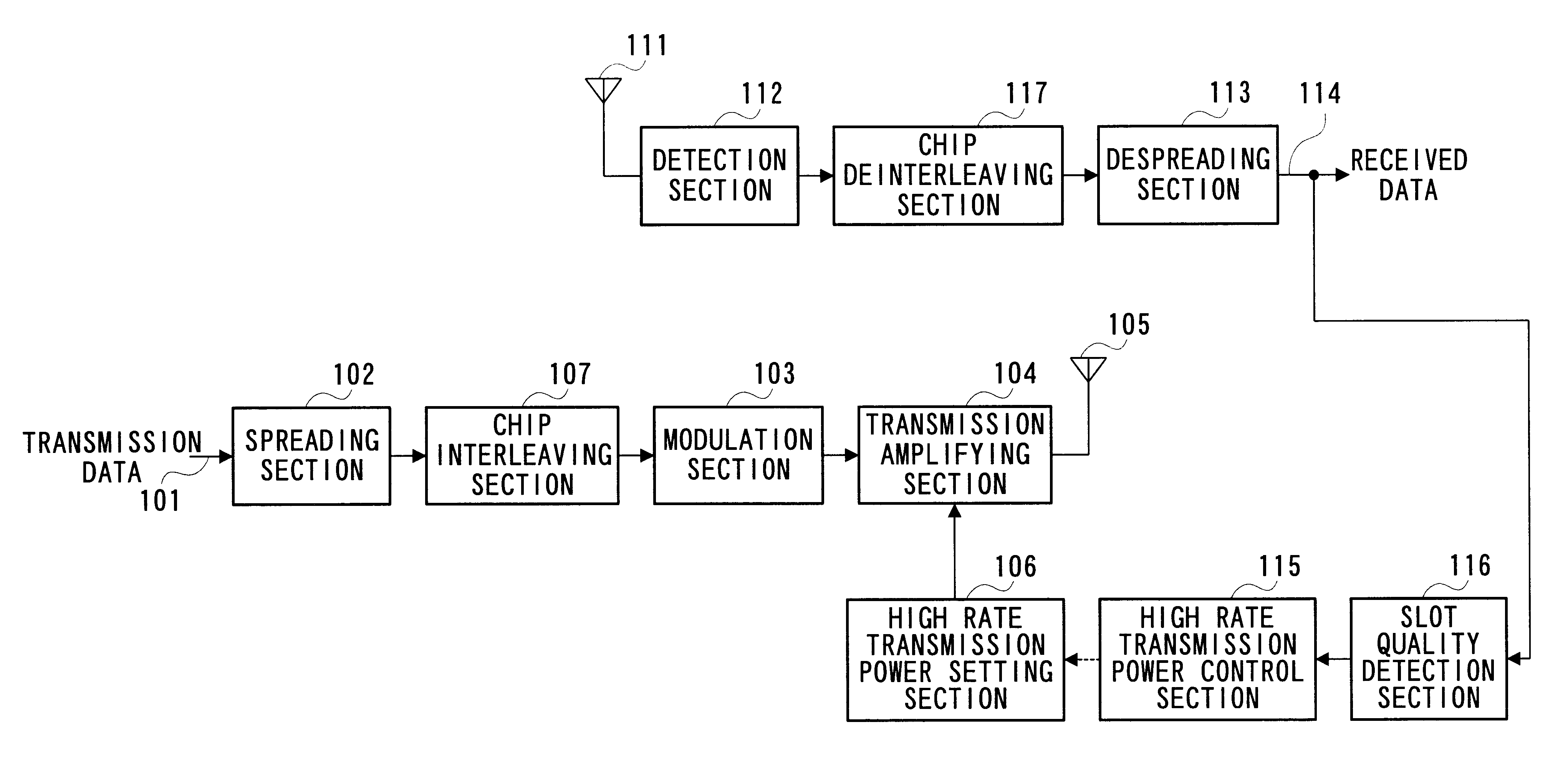
FIG. 5 is a block diagram illustrating a configuration of a CDMA radio communication apparatus according to Embodiment 1 of the present invention.

In a transmitter, transmission data 101 is spread at spreading section 102, and then subjected to chip interleaving processing at chip interleaving section 107. The interleaved signal is modulated at modulation section 103, amplified at transmission amplifying section 104 and then transmitted from transmission antenna 105.

In a receiver, a signal received at reception antenna 111 is detected at detection section 112, and then subjected to inverse arrangement to the chip interleaving at the transmission side, i.e., deinterleaving, at chip deinterleaving section 117. The deinterleaved data is combined at despreading section 113 to obtain received data 114. Further, the slot quality of received data 114 is detected at slot quality detection 116. Based on the detection result, high rate transmission power control section 115 generates a signal ...

embodiment 2

FIG. 7 is a block diagram illustrating a configuration of a CDMA radio communication apparatus according to Embodiment 2 of the present invention.

In a transmitter, transmission data 301 is spread at spreading section 302, and then subjected to chip interleaving processing at chip interleaving section 307. The interleaved signal is modulated at modulation section 303, amplified at transmission amplifying section 304 and then transmitted from transmission antenna 305.

In a receiver, a signal received at reception antenna 311 is detected at detection section 312, and then subjected to inverse arrangement to the chip interleaving at the transmission side, i.e., deinterleaving, at chip deinterleaving section 317. The deinterleaved data is combined at despreading section 313 to obtain received data 314. Further, the slot quality of received data 314 is detected at slot quality detection 116. Based on the detection result, low rate transmission power control section 315 generates a signal i...

embodiment 3

FIG. 10 is a block diagram illustrating a configuration of a CDMA radio communication apparatus according to Embodiment 3 of the present invention.

In a transmitter, transmission data 601 is spread at spreading section 602, and then subjected to chip interleaving processing at chip interleaving section 607. The interleaved signal is modulated at modulation section 603, amplified at transmission amplifying section 604 and then transmitted from transmission antenna 605.

In a receiver, a signal received at reception antenna 611 is detected at detection section 612, and then subjected to inverse arrangement to the chip interleaving at the transmission side, i.e., deinterleaving, at chip deinterleaving section 617. The deinterleaved data is combined at despreading section 613 to obtain received data 614. Further, the slot quality of received data 614 is detected at slot quality detection 616. Based on the detection result, transmission power decrement control section 615 generates a signal...


PUM


Abstract

In a CDMA transmission, a quality of each symbol of a frame is held constant by interleaving spread chip, while overhead and interference amounts in other cells are reduced by easing a rate of transmission power control. Further, transmission power is decreased by discontinuing transmission at the time the quality is satisfied, thereby increasing the system capacity. Furthermore, it is possible to achieve more remarkable effect by performing inverse transmission power control.

Description

BACKGROUND OF THE INVENTION1. Field of the InventionThe present invention relates to a CDMA radio communication system and method in a digital radio communication using the CDMA (Code Division Multiple Access).2. Description of the Related ArtFIG. 1 is a block diagram illustrating a configuration of a conventional CDMA radio communication system. In the CDMA radio communication system, at a transmission side, transmission data 1 is spread at spreading section 2. The spread signal is modulated at modulation section 3 and then amplified at transmission amplifying section 4. The resultant signal is transmitted from transmission antenna 5. An amplitude in transmission amplifier 4 is determined at high rate transmission power setting section 6.On the other hand, at a reception side, a signal received at reception antenna is detected at detection section 12 and then despread at despreading section 13. Received data 14 is thus obtained. Then, received data 14 is subjected to estimation of ...

Claims


Application Information

Patent Timeline
Patent Type & Authority Patents(United States)
IPC IPC(8): H04B7/26H04B1/707H04B1/69
CPCH04B7/2628H04B1/707Y02D30/70H04B1/69
Inventor KITAGAWA, KEIICHIUESUGI, MITSURU
Owner INVT SPE LLC
Why Eureka
Try Eureka