Telescoping escalator seismic restraint

Inactive Publication Date: 2003-10-28
SNEED TERRYLE L
View PDF7 Cites 70 Cited by
  • Summary
  • Abstract
  • Description
  • Claims
  • Application Information

AI Technical Summary

Problems solved by technology

If the escalator assembly is rigidly mounted between the adjacent floors of a building and no provision is made for relative movement between the escalator assembly and the building structure catastrophic failures can occur during an earthquake.
While the existing prior art escalator assembly designs are capable of meeting present code requiremen

Method used


Image

  • Telescoping escalator seismic restraint
  • Telescoping escalator seismic restraint
  • Telescoping escalator seismic restraint

Examples


Embodiment Construction

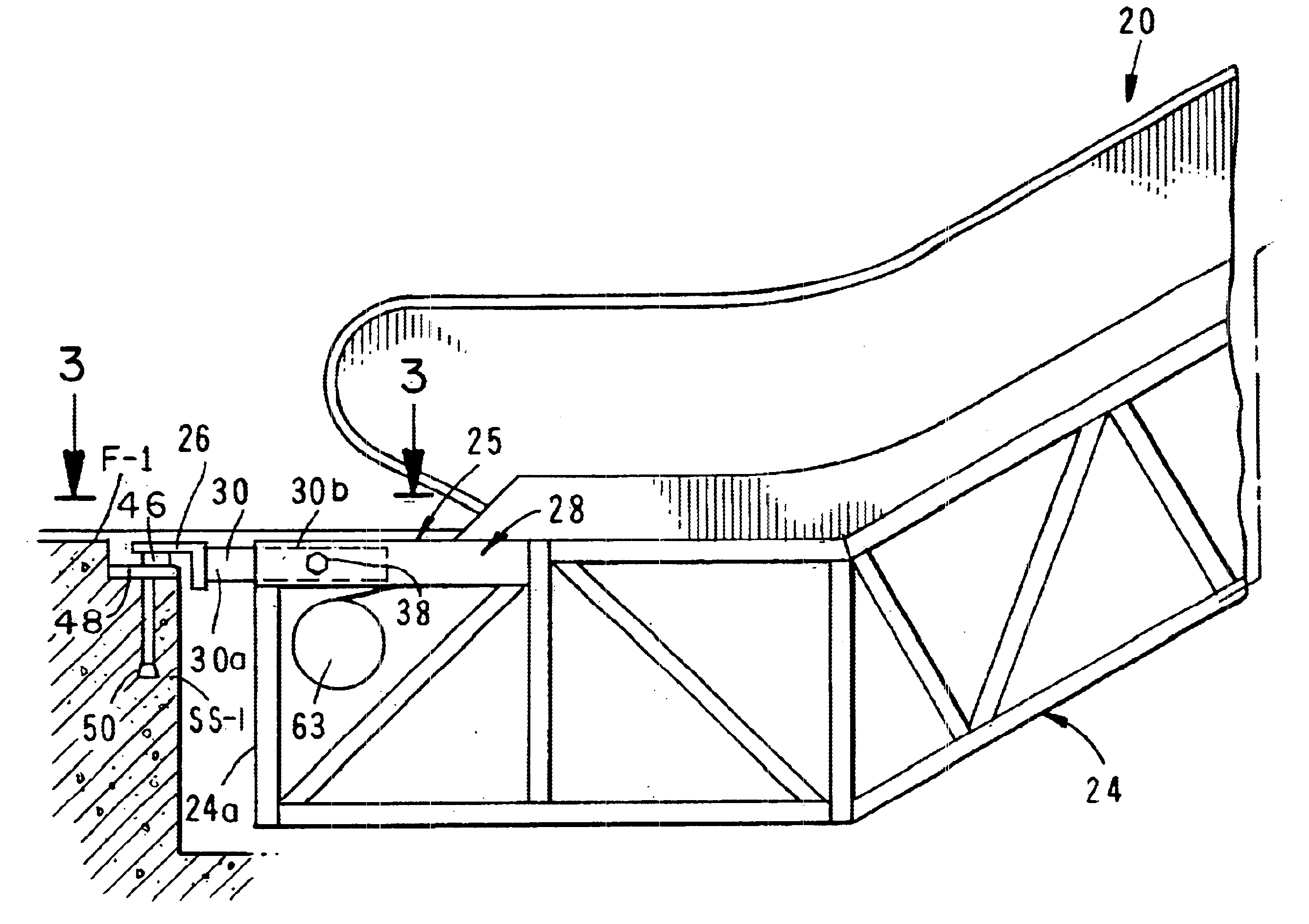
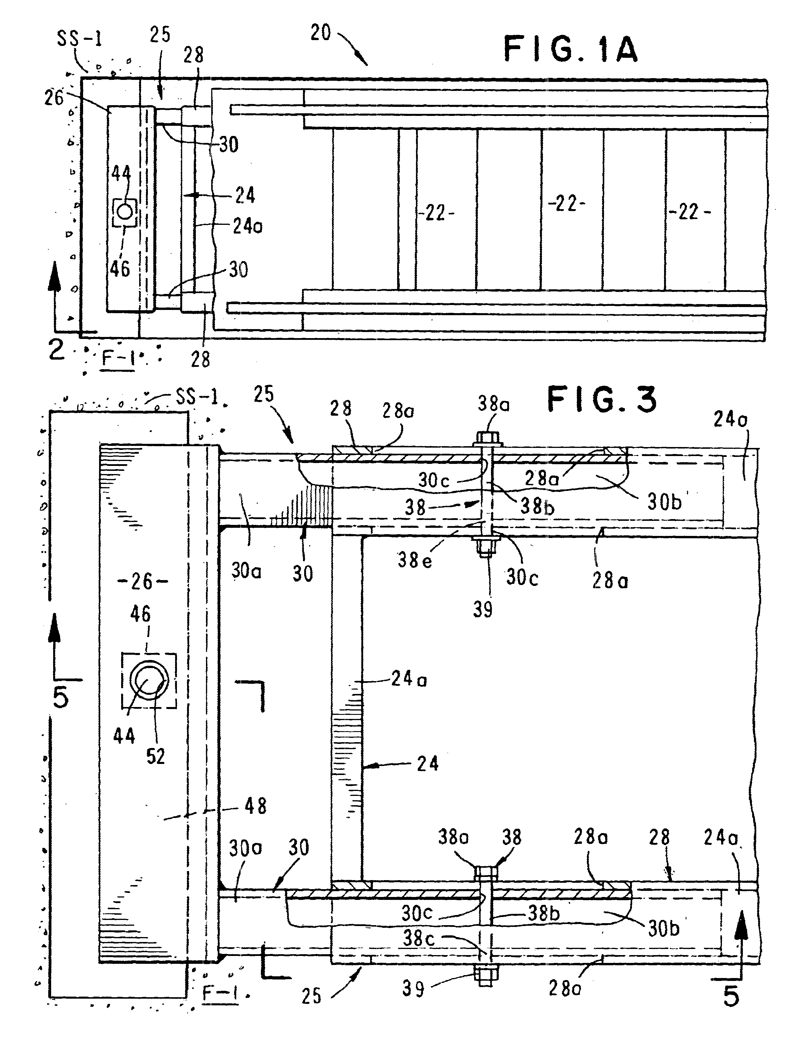
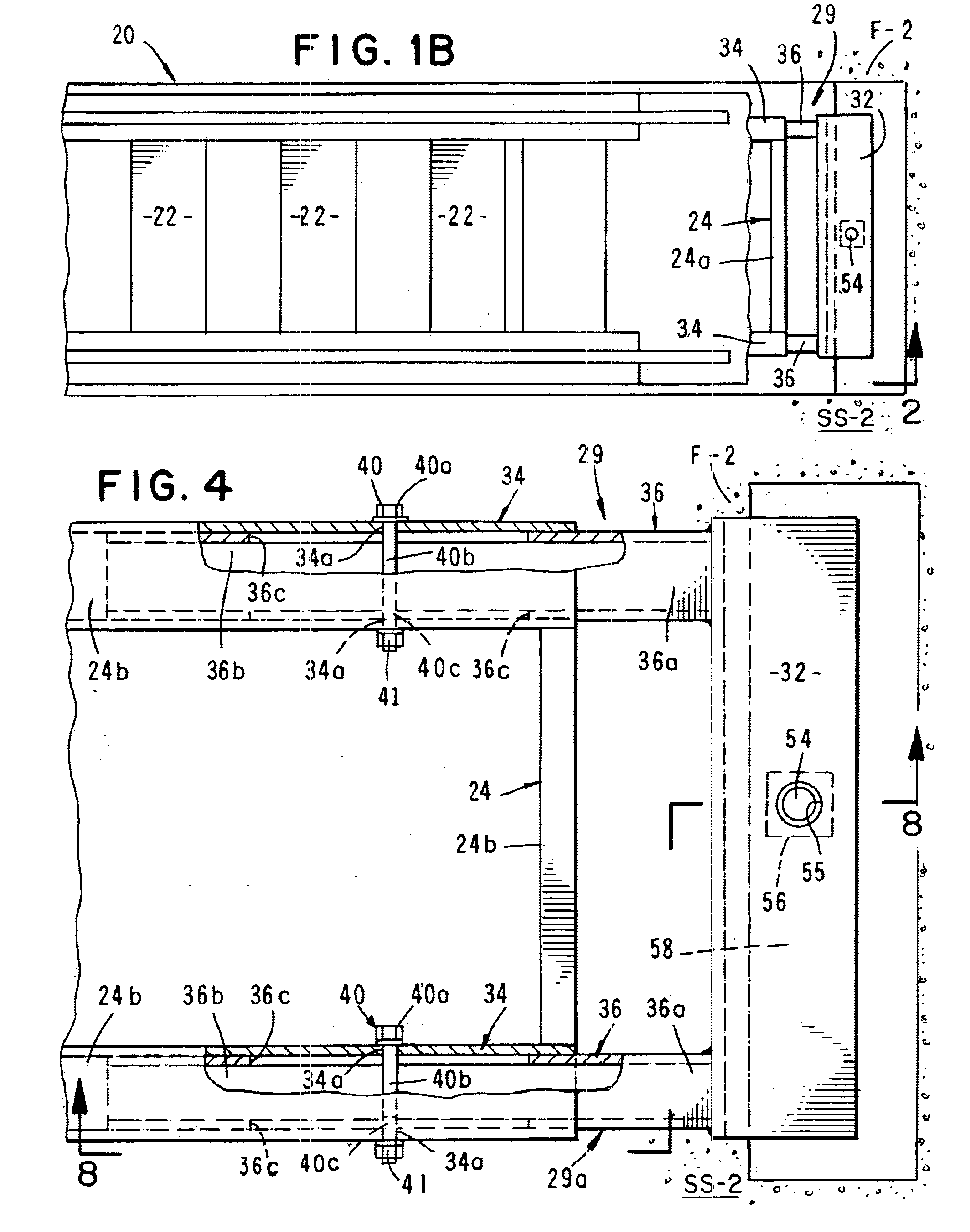
Referring to the drawings and particularly to FIGS. 1 through 4, one form of the apparatus of the invention is there shown. As best seen by referring to figures 1A, 1B, 1C and 1D, the apparatus of the invention here comprises an escalator 20 of a generally conventional construction having a plurality of moving treads 22, means for moving the plurality of moving treads and a pair of spaced apart supporting trusses 24 for supporting the plurality of moving treads (FIG. 3). Each of the trusses 24 has first and second ends 24a and 24b respectively and, as shown in FIGS. 2A and 2B, each is disposed between a first floor F-1 of a building having a structural support SS-1 and a second floor F-2 of a building having a structural support SS-2.

The improvement to the generally conventional escalator 20 here comprises a first connector means for connecting the first end 24a of each of the supporting trusses of the escalator to the structural support SS-1 of the first floor and a second connecto...


PUM


Abstract

An escalator or moving stairway that is constructed to accommodate oscillation and lateral displacement of a first story relative to a second story of a building between which the escalator or moving stairway extends such as which may occur during an earthquake. The escalator includes novel telescoping connector mechanisms that are connected at one end to a structural support of the building and are connected at the other end to supporting trusses of the escalator in a manner to permit relative movement between the supporting trusses and the floors of the first and second stories of the building.

Description

1. Field of the InventionThe present invention relates generally to moving stairways or escalators. More particularly, the invention concerns a novel connector mechanism for use in interconnecting an escalator system between spaced apart floors of a building.1. Discussion of the Prior ArtPrior art moving stairways or escalators escalators typically include a support truss and a plurality of interconnected steps that travel in a loop within the truss to provide a continuous movement along a specified path. When the escalator assembly is appropriately mounted between the floors of a building, relative motion of course exists between the moving steps and the stationary structure of the conveyor system. If the escalator assembly is rigidly mounted between the adjacent floors of a building and no provision is made for relative movement between the escalator assembly and the building structure catastrophic failures can occur during an earthquake. For this reason various states including C...

Claims


Application Information

Patent Timeline
IPC IPC(8): B66B23/00B65G21/00
CPCB65G21/00B66B23/00B65G2207/20
Inventor SNEED, TERRYLE L.
Owner SNEED TERRYLE L
Why Eureka
Try Eureka