Method and system for ensuring reception of a communications signal
What is AI technical title?
AI technical title is built by Patsnap AI team. It summarizes the technical point description of the patent document.
a communication signal and transmission method technology, applied in the field of electromagnetic communications, can solve problems such as potential problems and unlimited number of transmitters in this band
Inactive Publication Date: 2003-11-11
PARKER VISION INC
View PDF534 Cites 125 Cited by
Summary
Abstract
Description
Claims
Application Information
AI Technical Summary
This helps you quickly interpret patents by identifying the three key elements:
Problems solved by technology
Method used
Benefits of technology
Problems solved by technology
As such, there is a potentially unlimited number of transmitters in this band that are transmitting unwanted jamming signals.
Jamming problems are not limited to this band and can be a potential problem at any frequency.
Method used
Image
Click on the blue label to locate the original text in one second.
Reading with bidirectional positioning of images and text.
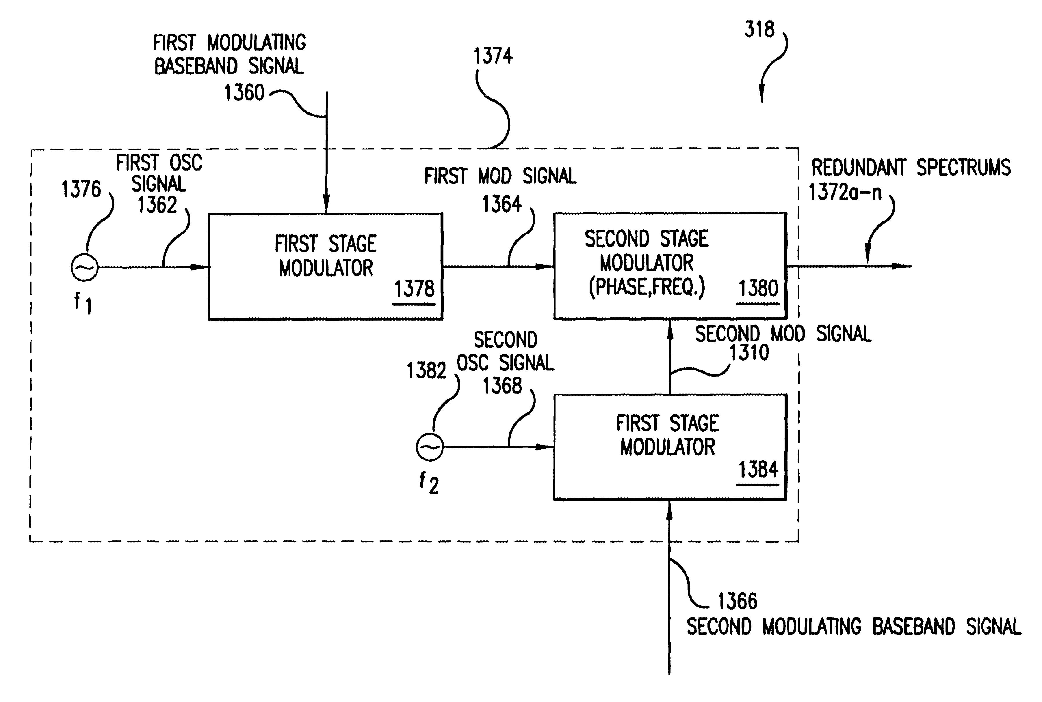
4.2.1.2.2 Second Stage Modulator (Replicator Modulator)
4.2.1.2.2.1 First embodiment: Replicating the Modulated Spectrum by Phase Modulating the Modulated Signal.
4.2.1.2.2.1.1 Operational Description
4.2.1.2.2.1.2 Structural Description
4.2.1.2.2.2 Second embodiment: Replicating the Modulated Spectrum by Frequency Modulating the Modulated Signal.
4.2.1.2.2.2.1 Operational Description
4.2.1.2.2.2.2 Structural Description
4.2.1.2.2.3 Other Embodiments
4.2.1.3 Implementation Examples
4.2.1.3.1 First Stage Modulator
4.2.1.3.1.1 AM Modulator as a Transistor Oscillator with a Variable Resistor
4.2.1.3.1.2 FM Modulator as a Voltage Controlled Crystal Oscillator
4.2.1.3.1.3 PM Modulator as a Tunable Filter
4.2.1.3.1.4 Other Implementations
4.2.1.3.2 Second Stage Modulator (Replicator Modulator)
4.2.1.3.2.1 PM Modulator as a Tunable Filter
4.2.1.3.2.2 Other Implementations...
first embodiment
5.2.1 First Embodiment of Processing Redundant Spectrums
5.2.1.1 Operational Description
5.2.1.2 Structural Description
5.2.2 Other Embodiments
5.2.3 Implementation Examples
5.2.3.1 Frequency Up-conversion
5.2.3.2 Other Implementations
6 Recovering a Demodulated BasebandSignal from the Redundant Spectrums that have Substantially the Same Information content
6.1 High Level Description
6.1.1 Operational Description
6.1.2 Structural Description
6.2 Example Embodiments
6.2.1 Down-conversion
6.2.1.1 Down-conversion by Mixing Redundant Spectrums with an Oscillating Signal
6.2.1.1.1 Operational Description
6.2.1.1.2 Structural Description
6.2.1.2 Down-conversion Using a Universal Frequency Translation Module
6.2.1.3 Other Embodiments
6.2.2 Spectrum Isolation
6.2.2.1 Spectrum Isolation by Filtering Redundant Spectrums
6.2.2.1.1 Operational Description
6.2.2.1.2 Structural Description
6.2.2.2 Down-conversion and Spectrum Isolation using a Unified Down-converting and Filtering Module (UDF)
6.2.2.3 Other Embodiment...
PUM
Abstract
The present invention includes a system and method for ensuring reception of a communications signal. A modulating basebandsignal with desired information is accepted, and a plurality of redundant spectrums is generated. Each redundant spectrum comprises the necessary amplitude, phase, and frequency information to substantially reconstruct the modulating basebandsignal. It is expected but not required that the redundant spectrums will be generated at a first location and sent to a second location over a communications medium. At the second location, the redundant spectrums are independently processed to recover a demodulating baseband signal for each of the redundant spectrums. In one embodiment, an error detection process is employed at the second location to detect and eliminate those demodulated baseband signals that have been corrupted during transmission. An error-free demodulated baseband signal is selected from the remaining demodulated baseband signals. The error-free demodulated baseband signal is representative of the modulating baseband signal sent over the communications medium.
Description
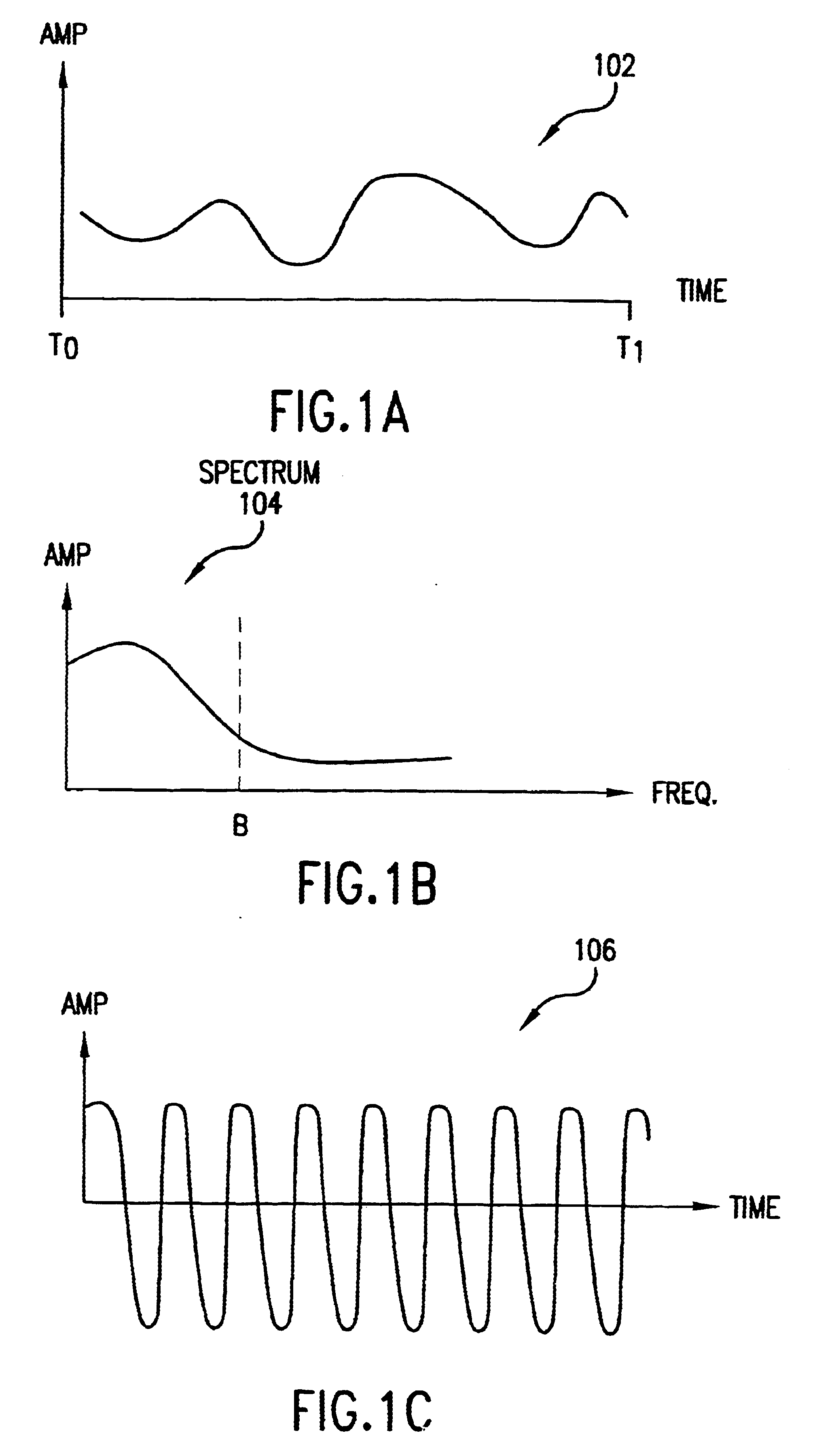
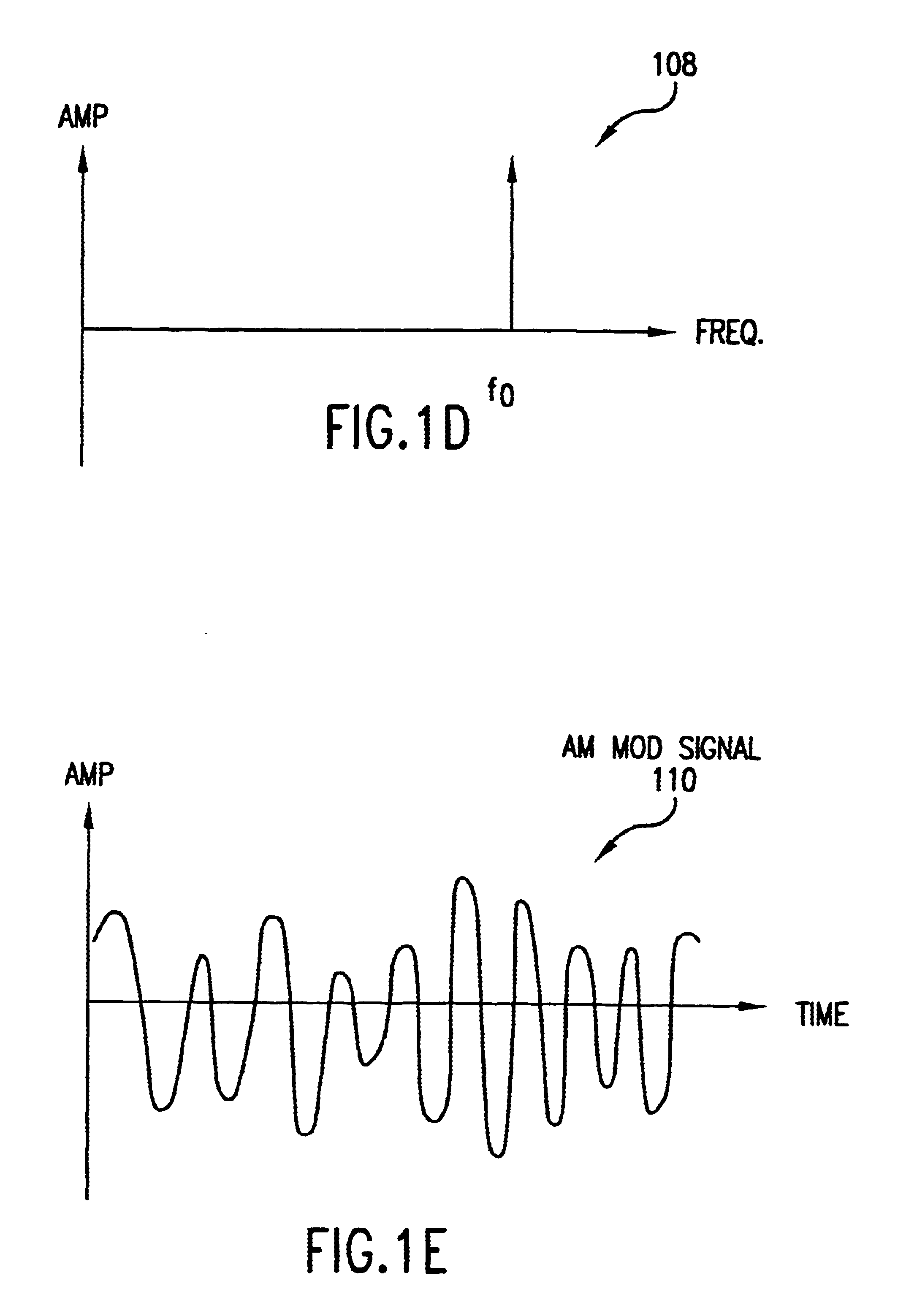
I. Field of the InventionThis is a continuation of pending application Ser. No. 09 / 176,415, filed Oct. 21, 1999The present invention relates generally to electromagnetic communications, and more particularly, to a method and system for ensuring reception of a communications signal.II. Description of the Related ArtCommunication links utilize electromagnetic signals (EM), in the form of electromagnetic waves, to carry analog or digital electronic information from a first location to a second location. In doing so, a baseband signal, containing the information to be transmitted, is impressed on an oscillating signal to produce a modulated signal at the first location. The modulated signal is sent over the communications link to the second location. At the second location, the modulated signal is typically down-converted to a lower frequency, where the baseband signal can be recovered.All EM signals can be sufficiently described in both the time domain and the frequency domain. FIG. 1A...
Claims
Application Information
Patent Timeline
Application Date:The date an application was filed.
Publication Date:The date a patent or application was officially published.
First Publication Date:The earliest publication date of a patent with the same application number.
Issue Date:Publication date of the patent grant document.
PCT Entry Date:The Entry date of PCT National Phase.
Estimated Expiry Date:The statutory expiry date of a patent right according to the Patent Law, and it is the longest term of protection that the patent right can achieve without the termination of the patent right due to other reasons(Term extension factor has been taken into account ).
Invalid Date:Actual expiry date is based on effective date or publication date of legal transaction data of invalid patent.
Patent Type & AuthorityPatents(United States)
IPC IPC(8): H03D7/00H04B7/12H04B7/02
CPCH04B7/12H03D7/00
InventorBULTMAN, MICHAEL J.COOK, ROBERT W.LOOKE, RICHARD C.MOSES, JR., CHARLEY D.SORRELLS, DAVID F.

