Device for recovery of forces generated by an aircraft engine

a technology of aircraft engine and force recovery, which is applied in the direction of machine supports, other domestic objects, transportation and packaging, etc., can solve the problems of difficult machining of parts of such large dimensions, withstand various stresses, and serious problems

Inactive Publication Date: 2003-11-18
AIRBUS OPERATIONS (SAS)
View PDF14 Cites 7 Cited by
  • Summary
  • Abstract
  • Description
  • Claims
  • Application Information

AI Technical Summary

Benefits of technology

This arrangement makes it possible to transmit the forces through symmetrical strut fittings of small dimensions, whose machining is simple and rapid. Furthermore, these independent strut fittings are lighter and thus easier to manipulate and mount on the strut.
The independence of the strut fittings makes it possible to channel the path of the forces from the attachment device to the wing or the fuselage, in a single principal direction. Thus a better division of forces is ensured. Each of the strut fittings is thus stressed in a balanced way, avoiding detrimental structural fatigue.

Problems solved by technology

Furthermore, it has to withstand various stresses such as aerodynamic drag, minimum mass and cost for maximum safety.
However, the large dimensions then required of the rib could lead to serious problems.
The machining of a part of such large dimensions is difficult and very long since machining has to take place in the mass.
Furthermore, such a part is heavy, bulky and costly.
In addition, it is difficult to mount.
This requires using a totally rigid fitting, to avoid problems of cracks and breaks, which increases the mass even further.

Method used


Image

  • Device for recovery of forces generated by an aircraft engine
  • Device for recovery of forces generated by an aircraft engine
  • Device for recovery of forces generated by an aircraft engine

Examples


Embodiment Construction

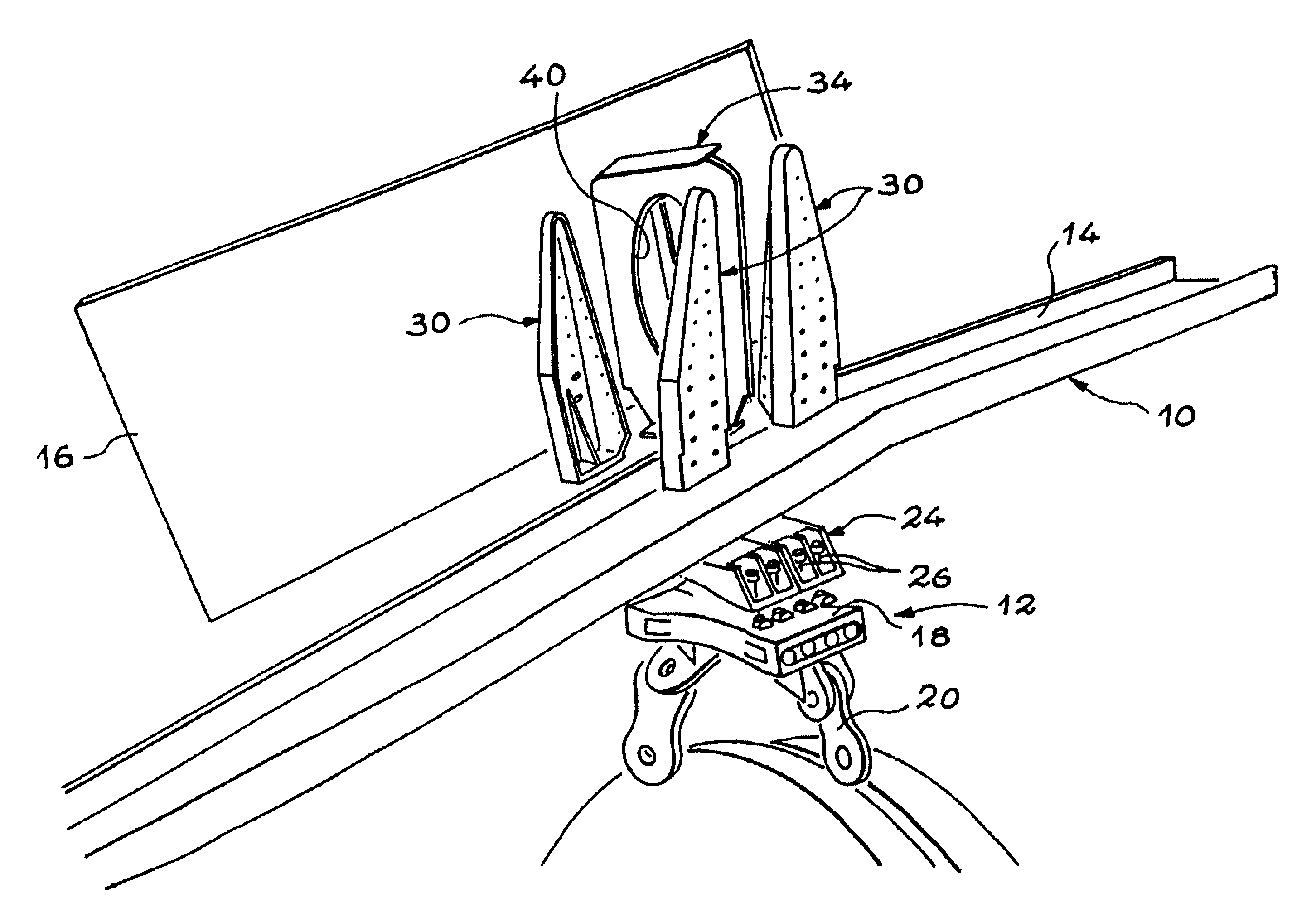
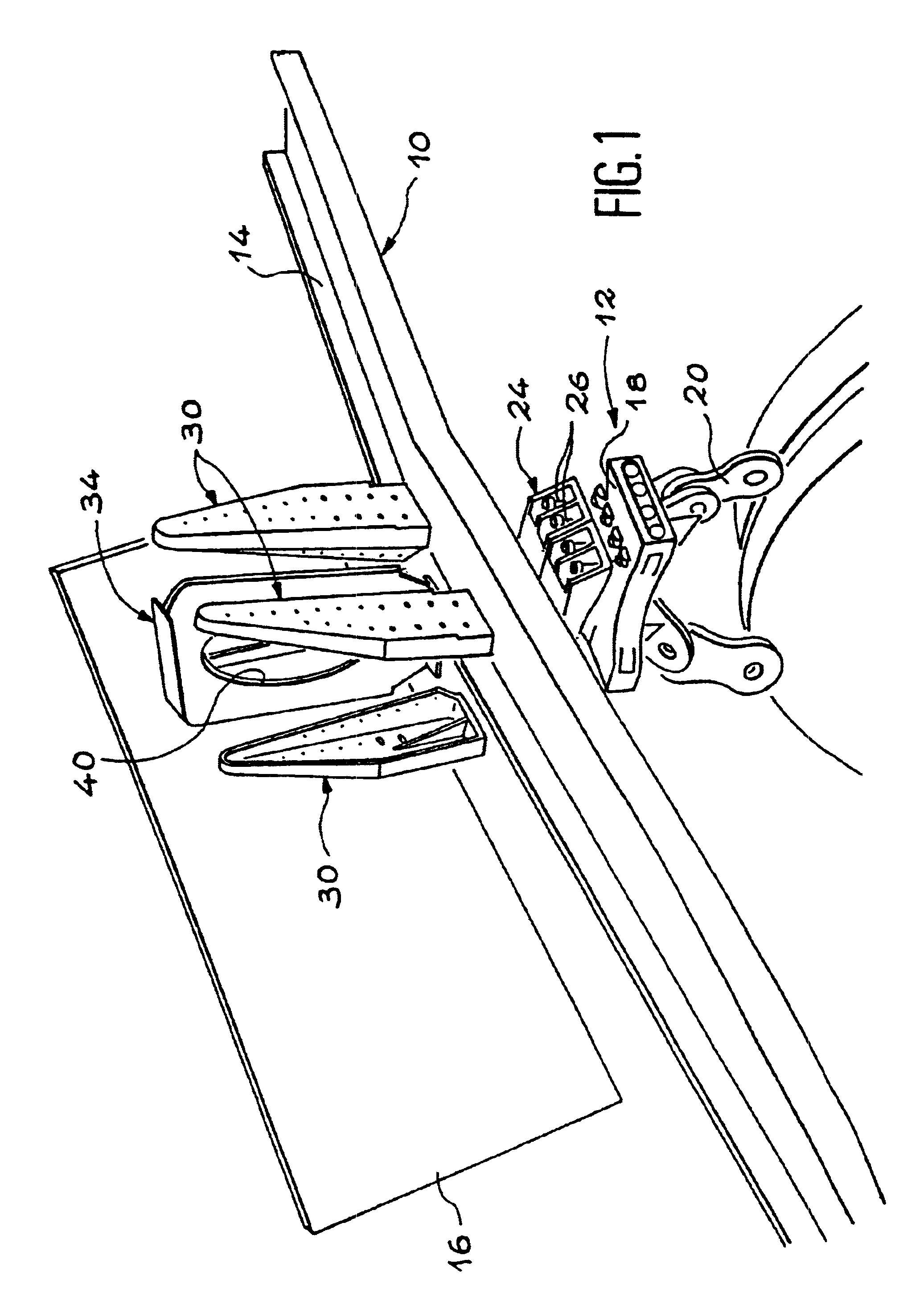
The precise aim of the invention is a device for recovering forces generated by an aircraft engine, with an original design making it possible to simplify its machining and mounting, and to limit its weight, its bulk and its cost, when the size of the engine leads to an increase in the dimensions of the intermediate fitting.

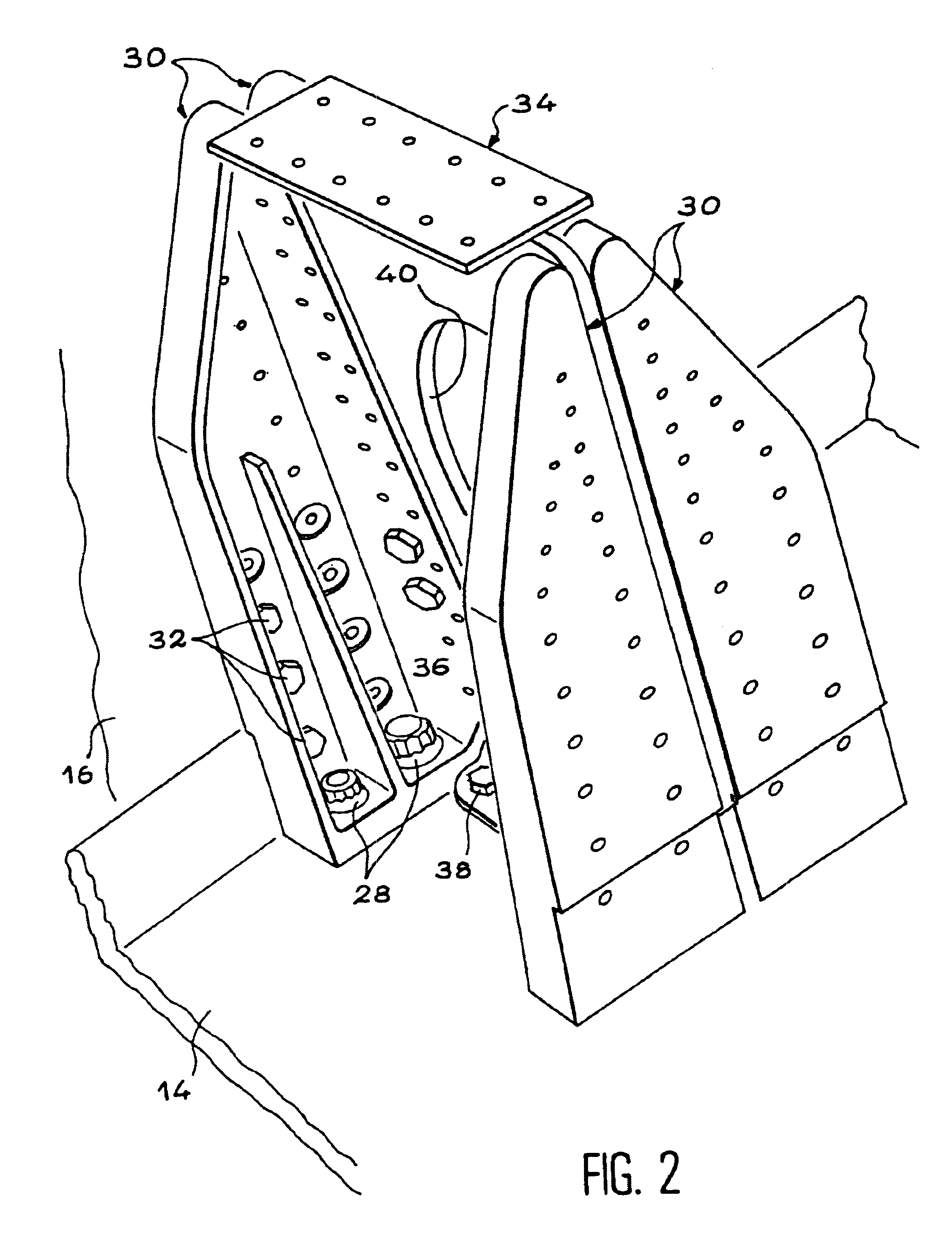
According to the invention, this result is obtained by means of a device for recovering the forces generated by an aircraft engine, comprising an engine strut able to be fixed to a structure of the aircraft and at least one attachment device fixed to the engine strut and capable of supporting the engine, the attachment device comprising an intermediate fitting fixed to the strut by first fixation means, characterised in that the engine strut comprises, facing the attachment device, several strut fittings independent from each other, the intermediate fitting being fixed to each of the strut fittings by the first fixation means.

This arrangement makes it possible to...


PUM


Abstract

A device for recovering forces generated by an aircraft engine has an engine strut (10), capable of being fixed to a wing or a fuselage of an aircraft, and an attachment device (12) fixed to the engine strut (10) and on which the engine is mounted. An intermediate fitting (24) of large dimensions, capable of recovering exceptionally high forces is fixed to several strut fittings (30) independent from each other, for example by bolts (28), across a lower spar (14) of the engine strut (10).

Description

The present invention relates to a device designed to recover the forces generated by an aircraft engine, in order to retransmit them to a structure of the aircraft, such as a wing or fuselage element, by means of an engine strut.More precisely, the invention relates to a device intended to recover the engine couple together with the forces produced by the engine along lateral and vertical directions relative to a longitudinal axis of the engine.STATE OF THE ARTEngines equipping aircraft are suspended under the wing or attached laterally onto the fuselage by means of an engine strut.The connection between the engine and the engine strut is ensured by systems generally constituted of two or three supplementary attachment devices, each fulfilling a certain function.Documents U.S. Pat. No. 5,620,154, U.S. Pat. No. 5,275,357 and U.S. Pat. No. 6,059,227 describe the different attachment devices existing at present. Each of these devices comprises a principle attachment structure and an e...

Claims


Application Information

Patent Timeline
Patent Type & Authority Patents(United States)
IPC IPC(8): B64D27/26B64D27/00
CPCB64D27/26B64D2027/266
Inventor LEVERT, STEPHANEROSZAK, SEBASTIEN
Owner AIRBUS OPERATIONS (SAS)
Why Eureka
Try Eureka