Clutch device for locks

a technology for locking devices and locks, applied in the direction of mechanical control devices, keyhole guards, instruments, etc., can solve problems such as configurations that complicate the form, number, or assembly of pieces

Inactive Publication Date: 2003-11-25
TALLERES DE ESCORIAZA SA
View PDF11 Cites 66 Cited by
  • Summary
  • Abstract
  • Description
  • Claims
  • Application Information

AI Technical Summary

Problems solved by technology

This leads to configurations which complicate the form, number, or assembly of the pieces; in addition to the fact that they are often valid only for solving the problem of improvements in features or technological adaptation that has motivated the modification in relation to a concrete type of lock and not to others with a similar application.

Method used


Image

  • Clutch device for locks
  • Clutch device for locks
  • Clutch device for locks

Examples


Embodiment Construction

With relation to the drawings and references enumerated above, two variants of embodiment of the proposed clutch for locks are illustrated in the attached drawings.

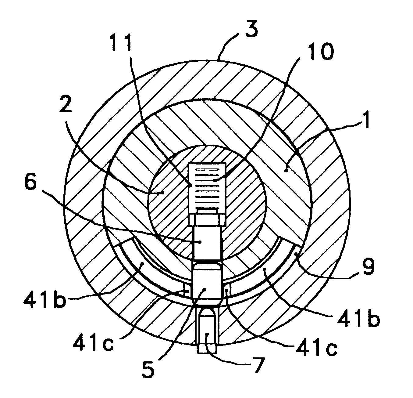
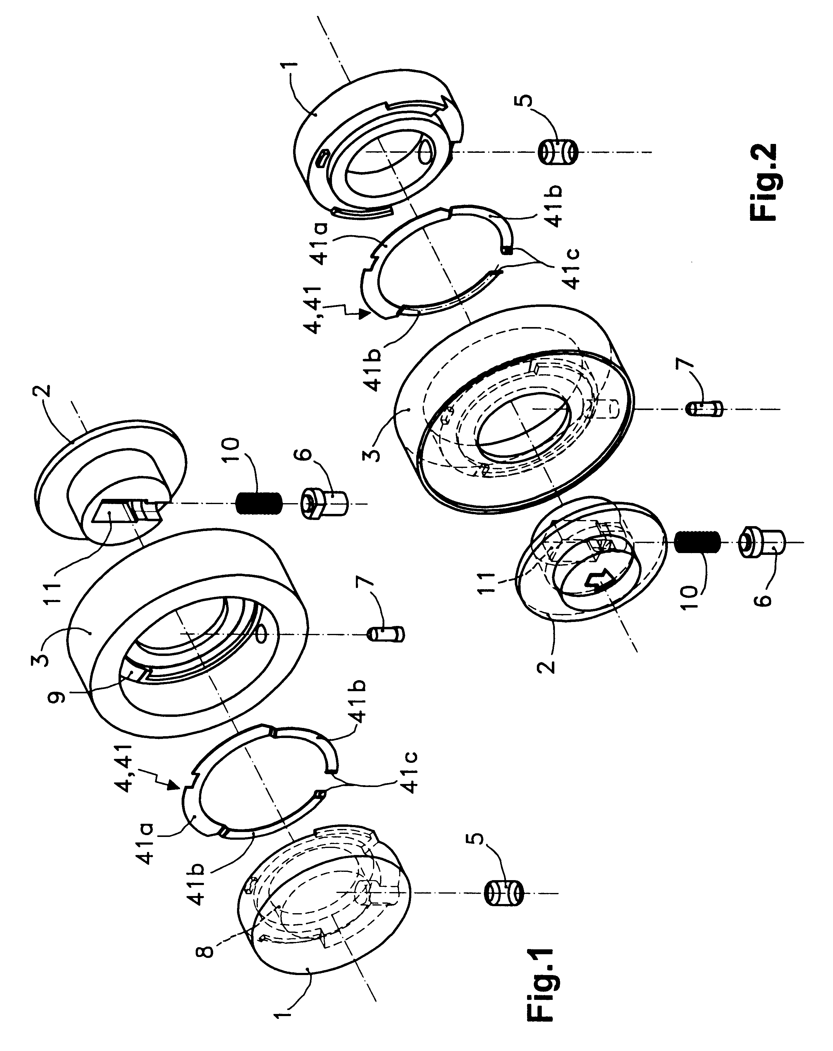
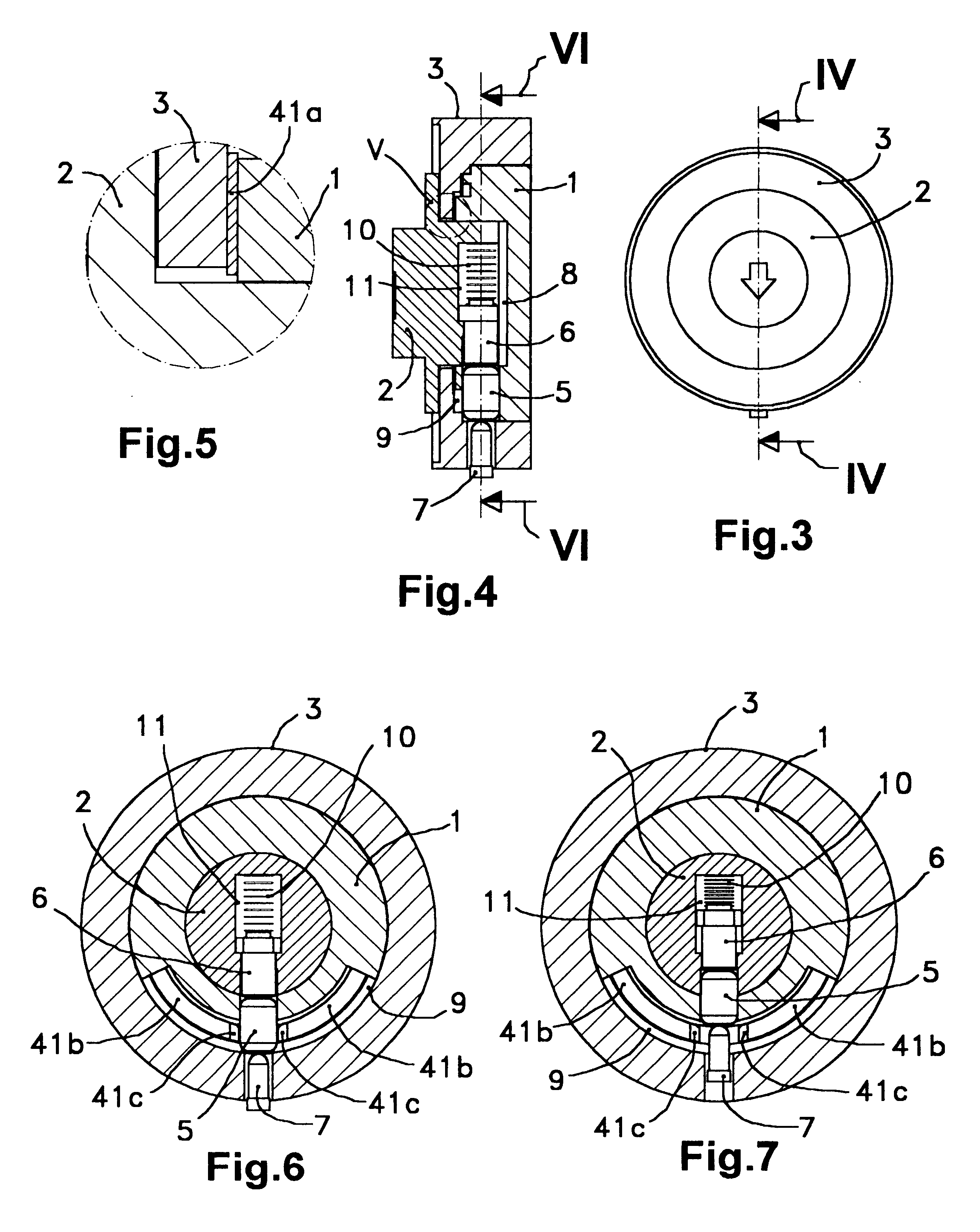
Referring to the first of these two variants of embodiment, FIGS. 1 and 2 clearly illustrate the characteristic construction of this clutch device, which consists of an interior axis (1), an exterior axis (2), a frame or static body (3), an elastic element (4), a radial trigger (5), a radial trigger lock (6) and a radial actuator (7); wherein: said interior axis (1), exterior axis (2) and static body (3) make up a coaxial assembly in which the exterior axis (2) penetrates, with a rotary adjustment, into an axial cavity (8) of the interior axis (1) while both axes (1, 2) are assembled with a rotary adjustment within the static body (3), said elastic element (4) is in a fixed relative position with respect to the static body (3) and in an annular housing (9) which is defined between this static body (3) and the interior axi...


PUM


Abstract

Clutch device for locks which consists of an interior axis, an exterior axis, a frame or static body, an elastic element, a radial trigger, a radial trigger lock and a radial actuator; wherein: the interior axis, exterior axis and static body comprise a coaxial assembly in which the exterior axis penetrates an axial cavity of the interior axis while both axes are assembled within the static body, the elastic element is in a fixed relative position with respect to the static body and in an annular housing defined between this static body and the interior axis, the radial trigger is lodged in a movable position within the interior axis and has a length equal to the difference between the exterior diameter of the exterior axis and the interior diameter of the static body, the radial trigger lock is installed within the exterior axis with its tip in the exterior diameter of this exterior axis and with its tail end placed against one end of a radial compression spring.

Description

This invention concerns a clutch device capable of determining the rotary coupling between a primary axis and a secondary axis, in such a manner that the primary axis can selectively rotate or not rotate while connected to the secondary axis.This device is specially designed for locks, whether mechanical or electromechanical, taking as the primary axis the axis which is inside the lock (interior axis) and as the secondary axis the one which is on the outside (exterior axis).PRIOR ARTIn this field, improvements in features or adaptation to more modern (electronic) technologies are frequently achieved on the basis of implementing modifications to the composition of existing locks, rather than presenting a new design.This leads to configurations which complicate the form, number, or assembly of the pieces; in addition to the fact that they are often valid only for solving the problem of improvements in features or technological adaptation that has motivated the modification in relation...

Claims


Application Information

Patent Timeline
Patent Type & Authority Patents(United States)
IPC IPC(8): E05B13/00E05B47/06
CPCE05B47/0692E05B13/005Y10T70/5677Y10T70/5805Y10T70/5823Y10T70/7062Y10T70/7102Y10T70/7107Y10T70/713E05B47/0607
Inventor ARAMBURU, LUIS ANGEL RUANOSAN MIGUEL, FERMIN MENTA
Owner TALLERES DE ESCORIAZA SA
Why Eureka
Try Eureka