
Medical device retaining sheath and medical device delivery system employing same

a medical device and retaining sheath technology, applied in the field of endoluminal prosthesis delivery systems, can solve the problems of inability to accurately deliver and deploy prosthesis, inability to accurately control the movement of the proximal to the distal end of the catheter, and inability to achieve the translation of control movements. , to achieve the effect of reducing the profile and yielding sufficient strength

Inactive Publication Date: 2011-11-01
BOSTON SCI SCIMED INC
View PDF53 Cites 70 Cited by
  • Summary
  • Abstract
  • Description
  • Claims
  • Application Information

AI Technical Summary

Benefits of technology

[0012]It is an advantage of the present invention to provide a catheter delivery system which delivers an endoluminal prosthesis to a target site without requiring the removal of an outer sheath or retaining structure.
[0013]It is also an advantage of the present invention to provide a delivery system for an endoluminal prosthesis which provides for delivery and expansion while still contained within the catheter sheath.
[0014]It is also an advantage of the present invention to provide an endoluminal prosthesis delivery system of reduced profile for effective delivery of a prosthesis through narrow body vessels.
[0015]It is a further advantage of the present invention to provide an endoluminal prosthesis delivery system which can remain implanted in a body vessel with the prosthesis.
[0016]In efficient attainment of these advantages, the present invention provides an endoluminal prosthesis delivery system comprising a tubular endoluminal prosthesis having a luminal surface and an opposed exterior surface, said prosthesis being radially expandable from a compressed condition under a first radially expansive force and a second radially expansive force greater than said first expansive force; and a delivery sheath maintaining said prosthesis in said compressed condition, said delivery sheath possessing a yield strength greater than said first expansive force of said prosthesis, and less than said second expansive force.
[0017]The present invention also provides a method of implanting an endoluminal prosthesis comprising loading a tubular endoluminal prosthesis in a reduced diameter in a compressed condition within a delivery sheath, said prosthesis being radially expandable under a first radially expansive force and a second radially expansive force greater than said first radially expansive force, said delivery sheath having a yield strength sufficient to retain said prosthesis in reduced diameter; intraluminally delivering said prosthesis to an implantation site wherein said second radially expansive force of said prosthesis is activated, said second radially expansive force being sufficient to surpass said yield strength of said delivery sheath.

Problems solved by technology

Delivery and removal of the catheter sheath, however, to implant and / or activate the prosthesis presents several problems.
First, catheter movement can disturb or move the introducer sheath at the wound site where the catheter is inserted into the vessel, thereby resulting in premature deployment of the prosthesis.
Secondly, in tortuous anatomy, the added friction caused by rubbing the outer catheter against the vessel can make delivery and deployment of the prosthesis difficult.
The translation of control movements from the proximal to the distal end of the catheter is imprecise, jerky and in some instances impossible due to the increased friction caused by tortuosity.
Thirdly, delivery of the sheathed prosthesis can create trauma to the endothelium over the entire length of the catheter.

Method used


Image

  • Medical device retaining sheath and medical device delivery system employing same
  • Medical device retaining sheath and medical device delivery system employing same
  • Medical device retaining sheath and medical device delivery system employing same

Examples


Embodiment Construction

[0035]The following is a detailed description of the preferred embodiments of the present invention. The description is meant to describe preferred embodiments, and is not meant to limit the invention in any way.

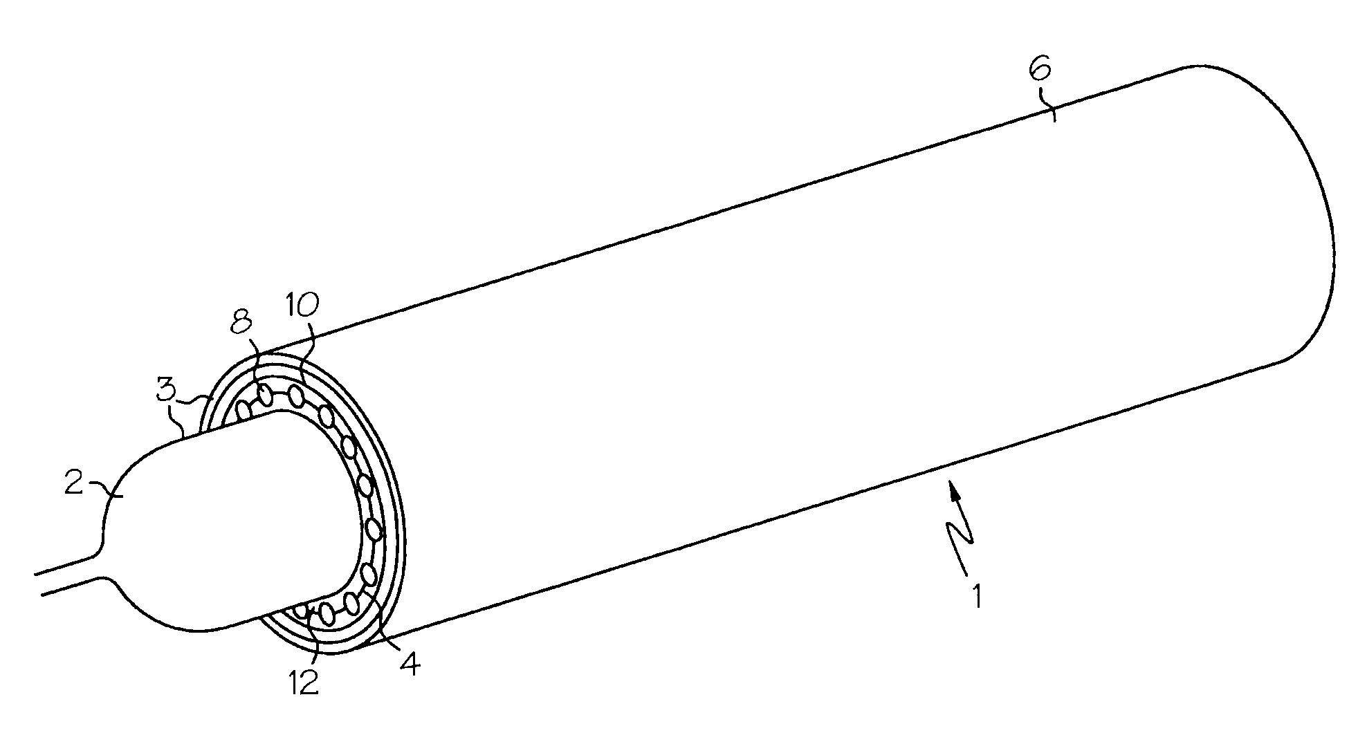
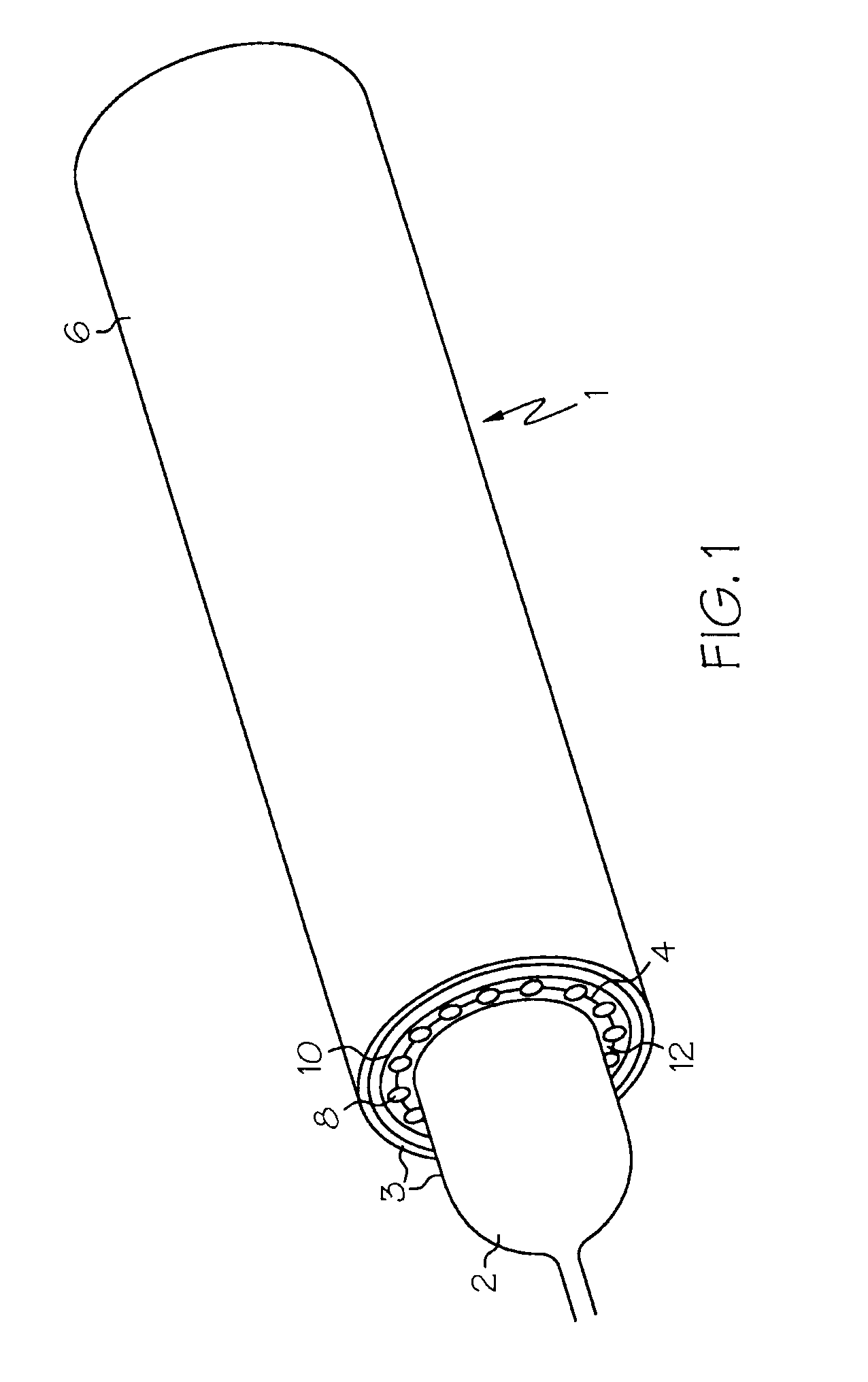
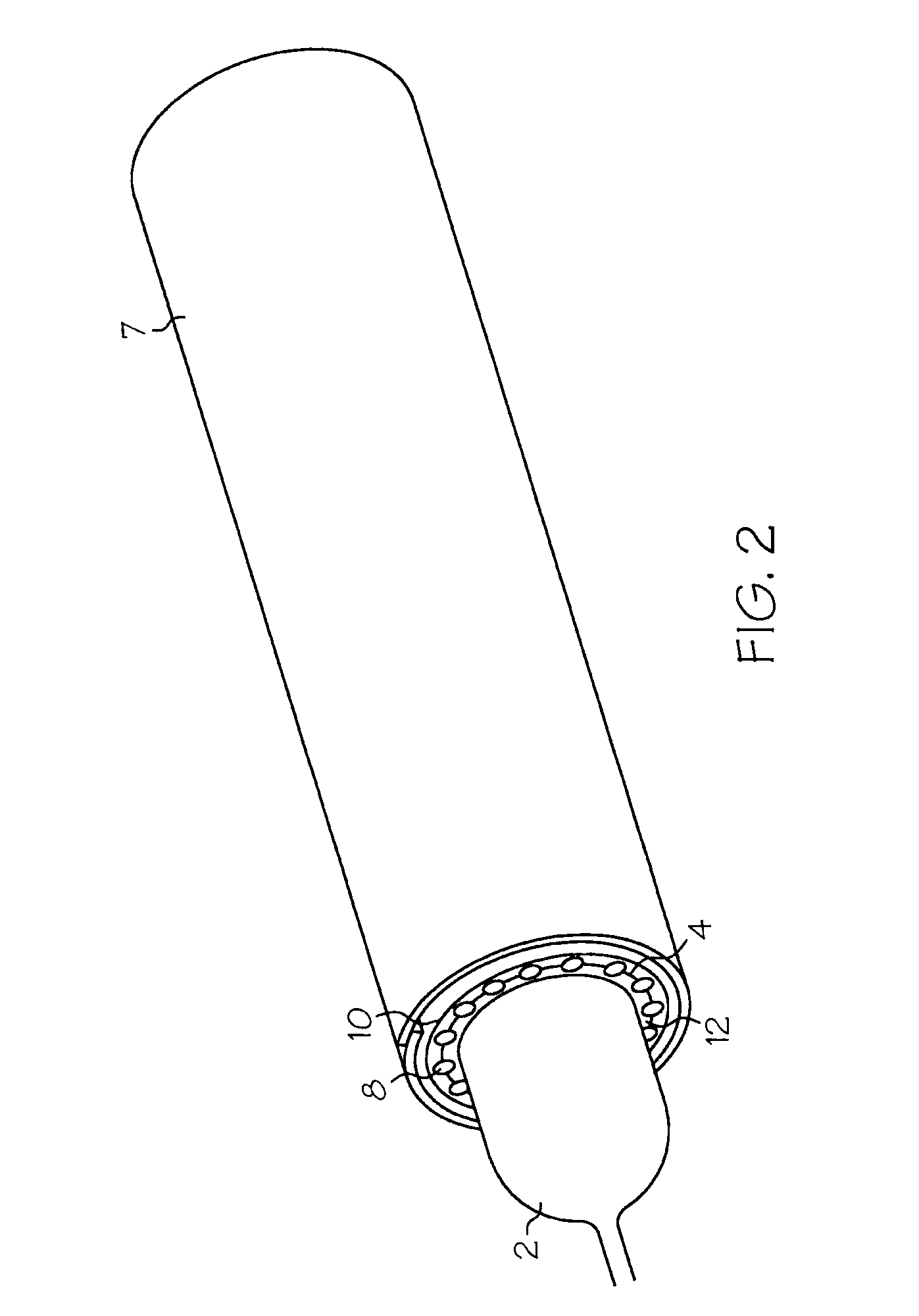
[0036]The present invention provides a system for delivery of an expandable prosthesis to a target site. The delivery system may include a catheter having an expandable balloon. The endoluminal prosthesis is supported over the balloon by a catheter sheath. The present invention provides a catheter sheath which has a yield strength greater than a first expansive force exhibited by the endoluminal prosthesis, but less than a second expansive force of either the balloon or of the prosthesis so as to retain the prosthesis in a collapsed condition during delivery and to provide for deployment of the expandable prosthesis upon application of the expansive force from the balloon without removal of the sheath.

[0037]Various prostheses may be employed in the present invention. A stent...


PUM

PropertyMeasurementUnit
yield strengthaaaaaaaaaa
bio-absorbableaaaaaaaaaa
shapeaaaaaaaaaa

Abstract

An endoluminal prosthetic delivery system provides a delivery sheath possessing a yield strength capable of allowing implantation of the prosthesis with increased efficiency. An endoluminal prosthesis is inserted in a body in a radially compressed condition, and expanded at an implantation site, whereby a delivery sheath or the prosthesis itself possesses a yield strength sufficient to allow radial expansion of the prosthesis. A method of implanting an endoluminal prosthesis is also herein provided.

Description

[0001]This application is a continuation of U.S. patent application Ser. No. 09 / 409,620 filed Oct. 1, 1999, now U.S. Pat. No. 6,533,806.FIELD OF THE INVENTION[0002]The present invention relates generally to a system and method of delivering an endoluminal prosthesis within a body lumen. More particularly the present invention provides a delivery device retaining an endoluminal prosthesis during delivery and additionally for the deployment of the endoluminal prosthesis at a target site within the lumen.BACKGROUND OF THE INVENTION[0003]Endoluminal prostheses are typically used to repair, replace, or otherwise correct a diseased or damaged blood vessel. An artery or vein may be diseased in a variety of ways. The prosthesis may therefore be used to prevent or treat a wide variety of defects such as stenosis of the vessel, thrombosis, occlusion, or an aneurysm.[0004]One type of endoluminal prosthesis used in treatment and repair of diseases in various blood vessels is a stent. A stent is...

Claims


Application Information

Patent Timeline
Patent Type & Authority Patents(United States)
IPC IPC(8): A61F2/06A61F2/00A61F2/02A61M25/12
CPCA61F2/07A61F2/97A61F2002/072A61F2002/075A61F2002/9511A61F2002/9583A61F2210/0004A61F2250/0018A61F2250/0071A61F2/89A61F2230/005
Inventor SULLIVAN, JASONGOLDS, ELLENTSENG, DAVIDBOATMAN, JEFF
Owner BOSTON SCI SCIMED INC
Learn More