Card, in particular chip card, reading device

Inactive Publication Date: 2003-11-25
CP8 TECH SA
View PDF14 Cites 24 Cited by
  • Summary
  • Abstract
  • Description
  • Claims
  • Application Information

AI Technical Summary

Benefits of technology

is to provide a card reader, particularly of a chip card, that eliminates the defects of the devices of the prior art, some of which have just been mentioned.
To this end, the card reader according to the invention, which includes a cover for protecting the keys of the keyboard and its display unit, is equipped with a flap integral with the cover that covers the insertion aperture when the device is not in use, which prevents the entry of undesirable elements into the device, even if the device is moved into a polluted environment.
In a preferred variant of the invention, the card reader is provided with a configuration such that it can be presented to a user so as to be inclined, which facilitates its handling and, in particular, the entry of a confidential code.

Problems solved by technology

The objects or polluting particles that may penetrate the card reader insertion slot are therefore capable of creating malfunctions, or even damaging some of these elements or circuits.
First of all, the general ergonomics of these devices are not optimal. In particular, card readers of the type that can be placed in the pocket of a garment must be as thin as possible and are generally in the shape of a rectangular parallelipiped. When they are placed on a table, it is relatively difficult to insert the card into the slot, and the access to the keys of the keyboard is not optimal, either.
Secondly, it often happens that the user forgets to remove his card after use, particularly after he has entered his confidential code by means of the keyboard. The card can remain inside the card reader without the card holder's noticing it, especially if the card reader is equipped with a cover.

Method used


Image

  • Card, in particular chip card, reading device
  • Card, in particular chip card, reading device
  • Card, in particular chip card, reading device

Examples


Embodiment Construction

)

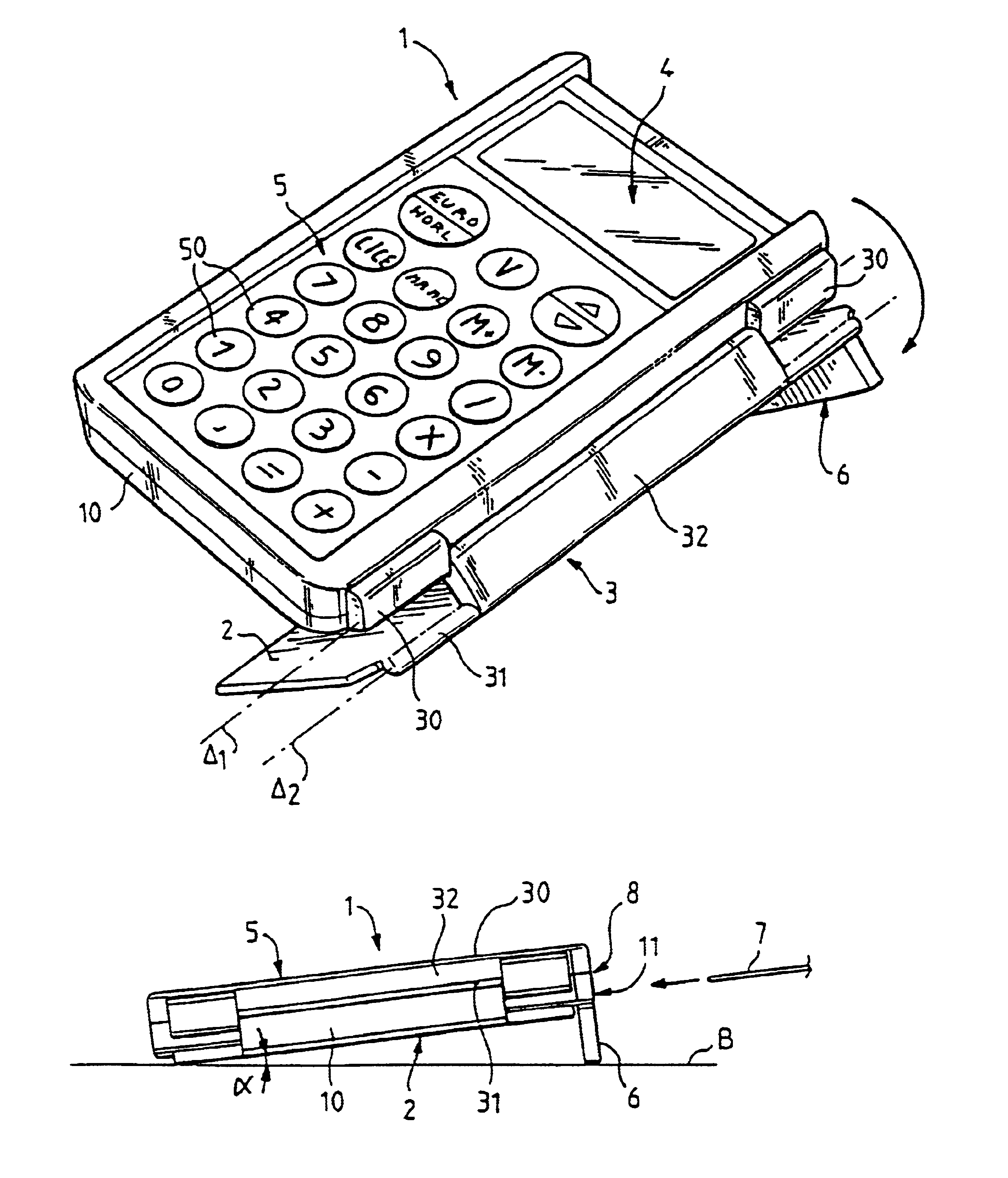
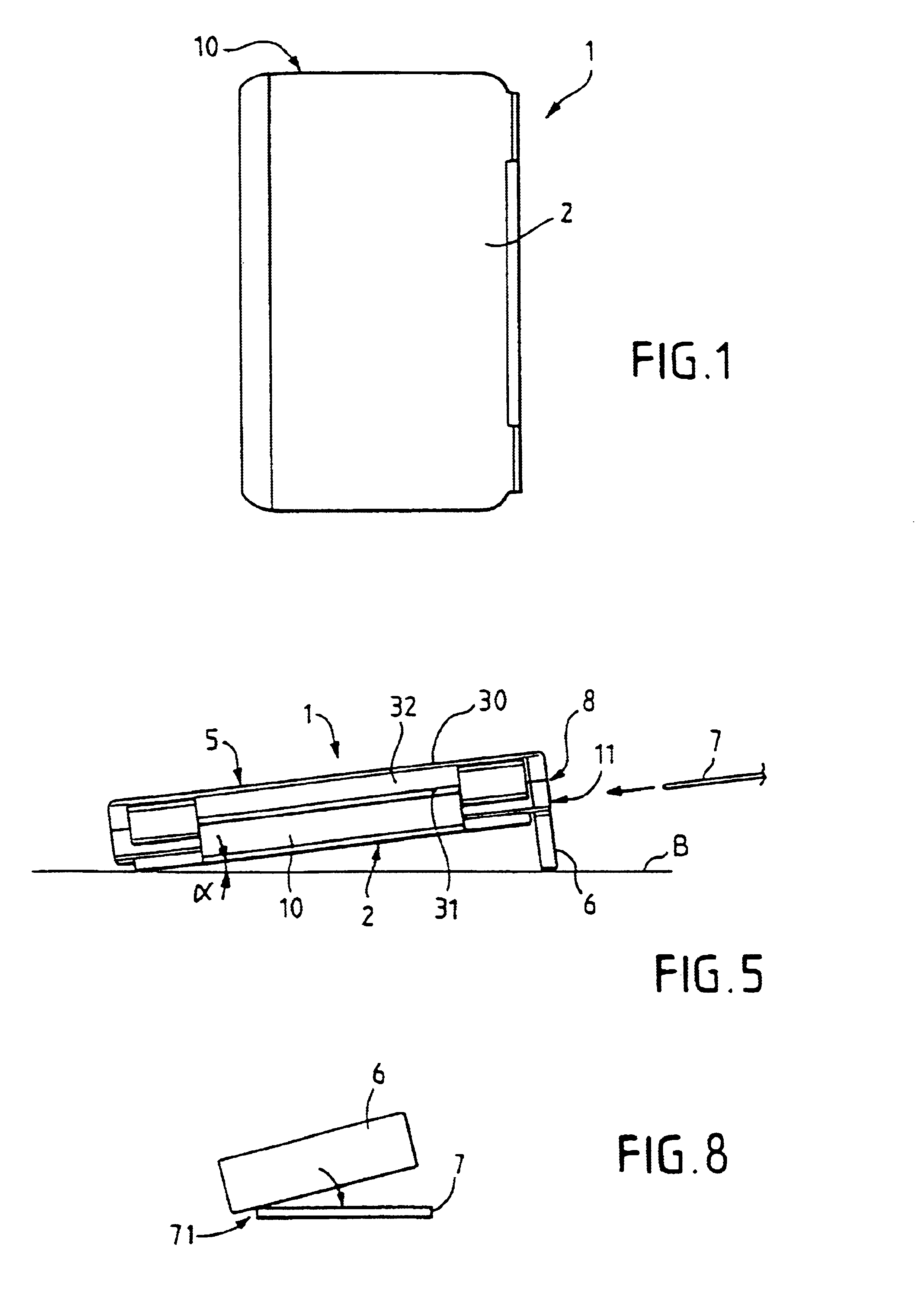
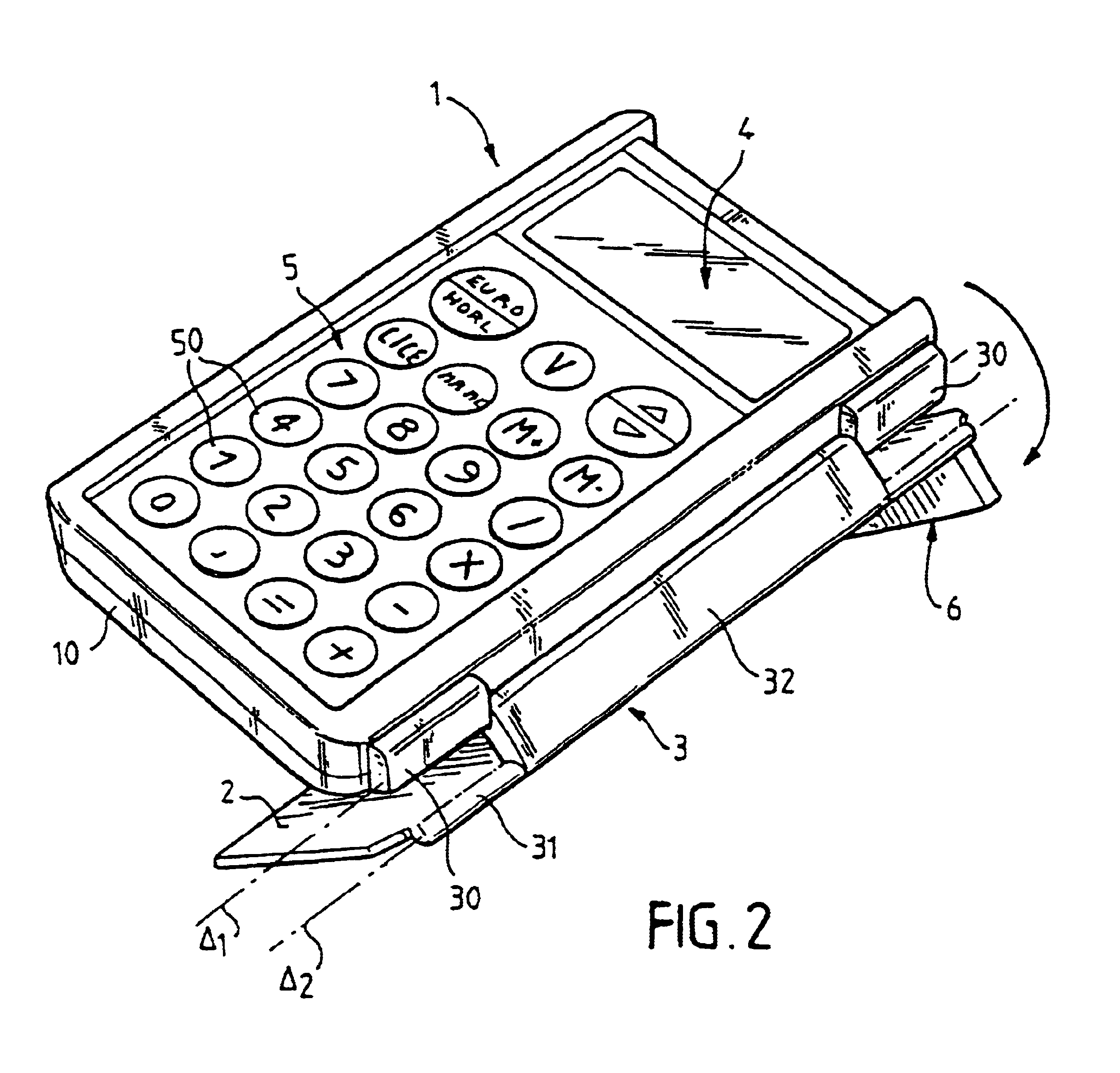
An exemplary embodiment of a card reader according to the invention will now be described in connection with FIGS. 1 through 5.

FIG. 1 illustrates the card reader 1 in the closed position (top view), and FIG. 2 (three-quarter top view in perspective) illustrates this same card reader in a position that will be called semi-open. In effect, the housing 10 of the card reader is equipped with a protective lid or cover 2. The latter is attached to the housing 10 by means of a hinge joint 3 disposed along one of the walls of this housing 10. More precisely, this joint comprises a double hinge, 30 and 31, whose operation and function will be described in detail below.

A card reader normally comprises a display unit 4, most often a liquid crystal display, and a data entry element constituted by a keyboard 5, and keys 50 (alphanumeric keys and function keys). The protective cover 2, in the example described, completely covers the keyboard 5 and the display unit 4 when it is in the closed posi...


PUM


Abstract

The invention relates to a card (7) reading device (1) comprising a housing (10) equipped with a keyboard (5), a display unit (4), a slot (8) for inserting a card (7) into the housing (10) and a cover (2) adapted to be pivoted between an open and closed position for protecting the keyboard (5) and the display unit (4), when in the closed position. The cover (2) includes an integral flap (6) and is attached to the housing (10) by an articulating element (3) that allows it to pivot between the closed position and open position and be brought into position underneath the housing (10) in the open position. The flap (6), which covers the insertion slot (8) when the cover (2) is closed, serves as a support base when in the open position to incline the housing (10) when the reading device is placed on a support surface such as desk or table.

Description

1. Field of the InventionThe present invention relates to a card reading device, particularly a chip card reader.Within the scope of the invention, the term "card" should be understood in its most general sense: magnetic stripe card, "smart" card, "chip" card, etc. It should also be understood that the term "card reader" is generic: it relates to any device that can read and / or write onto cards of the aforementioned types.Likewise, the applications of these cards are quite diverse: banking or similar applications, electronic purses, security badges, etc. In France, in particular, it is customary to provide all those eligible for social security with a short- or intermediate-term "chip" card storing a certain amount of information of a medical and / or administrative nature.2. Description of Related ArtFor about twenty years or so, these various types of cards, particularly the cards equipped with an "electronic chip," i.e., with a controller or microprocessor associated with storage c...

Claims


Application Information

Patent Timeline
IPC IPC(8): G06K7/00G06F17/40H05K5/03G06K13/06G06K17/00
CPCG06K7/006G06K7/0013
Inventor CHOISET, BRUNO
Owner CP8 TECH SA
Why Eureka
Try Eureka