Fastener manufacturing apparatus and method

Active Publication Date: 2006-11-09
WHITESELL FORMED COMPONENTS
View PDF15 Cites 9 Cited by
  • Summary
  • Abstract
  • Description
  • Claims
  • Application Information

AI Technical Summary

Benefits of technology

[0009] Pilot lines used to determine the effectiveness of, more specifically, the inspection station set forth above, have reduced the number of defective fasteners affixed to the continuous strip to nearly zero per thousand fasteners from upward of dozen per thousand fasteners.
[0010] A still further improvement over the prior art wire installation assemblies makes use of a re-groover to reform the continuous groove formed by adjacent nuts into which a carrier wire is inserted. In the cutting station of the die press, the continuous groove formed in the rod is known to be deformed by the die press resulting in an inconsistent installation of the wire by the wire insertion device. This inconsistent installation of the wire along the continuous groove formed by adjacent fasteners is known to result in broken wire at the end user causing a manufacturing defect in the tooling used to affix the fasteners to a product. By reforming the groove, a consistent, continuous groove is formed between adjacent fasteners enabling the uniform installation of the carrier wire further enabling a uniform knurling affixation of the wire eliminating defects associated with the inconsistent affixation set forth above.

Problems solved by technology

Prior art inspection stations merely determine the existence of an aperture in an individual fastener and are not capable of determining the quality of the helical rib disposed within the aperture.
In the cutting station of the die press, the continuous groove formed in the rod is known to be deformed by the die press resulting in an inconsistent installation of the wire by the wire insertion device.
This inconsistent installation of the wire along the continuous groove formed by adjacent fasteners is known to result in broken wire at the end user causing a manufacturing defect in the tooling used to affix the fasteners to a product.

Method used


Image

  • Fastener manufacturing apparatus and method
  • Fastener manufacturing apparatus and method
  • Fastener manufacturing apparatus and method

Examples


Embodiment Construction

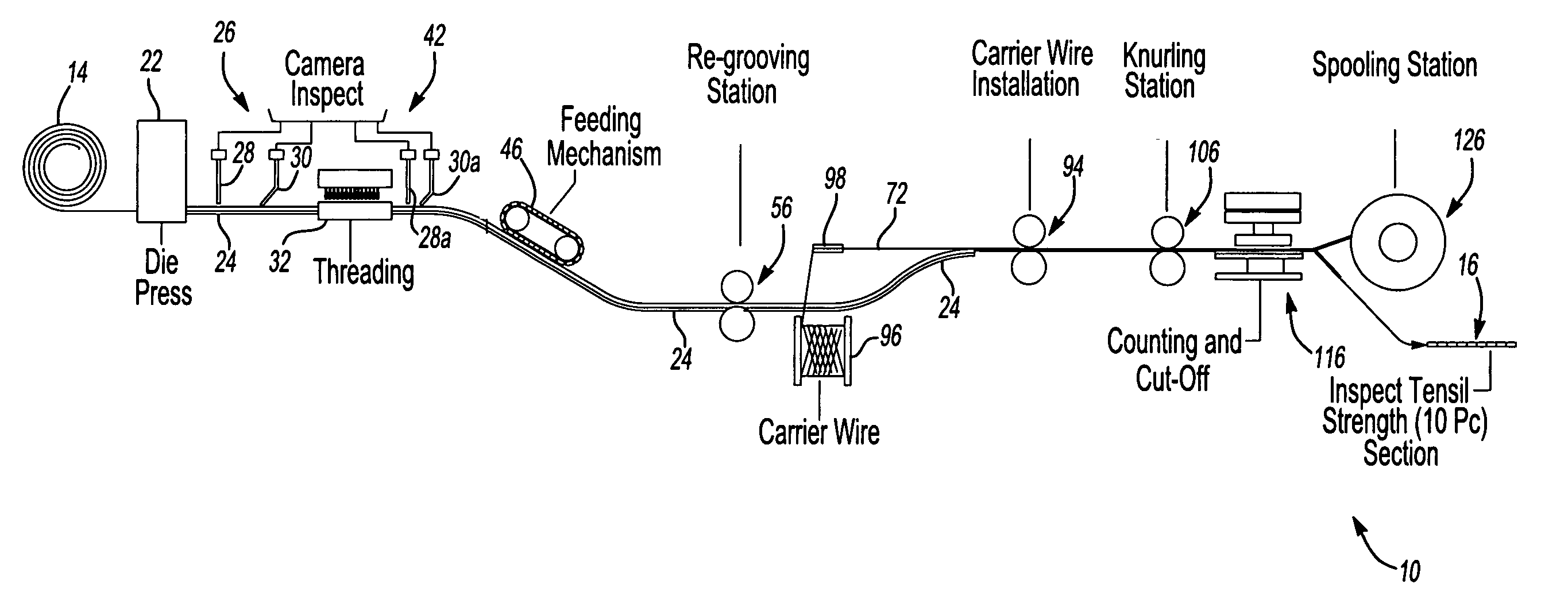
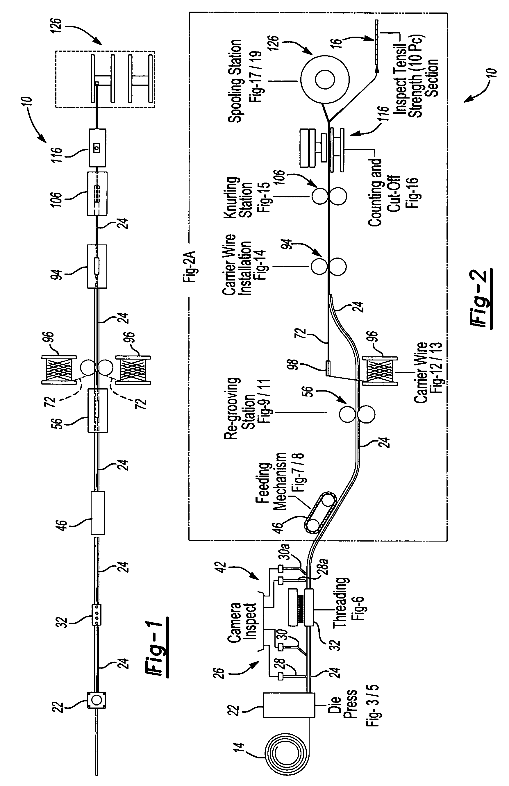
[0037] Referring to FIGS. 1 and 2, one preferred embodiment of the inventive assembly for manufacturing fasteners is generally shown at 10. The assembly 10 provides a method of continuously manufacturing, for example, pierce nuts 12 (FIG. 3) from a coiled rod 14 resulting in a continuous strip 16 of fasteners (fastener strip, see FIGS. 17 and 18) for use in a production facility where pierce nuts 12 are mechanically locked to sheet metal at a high rate of speed.

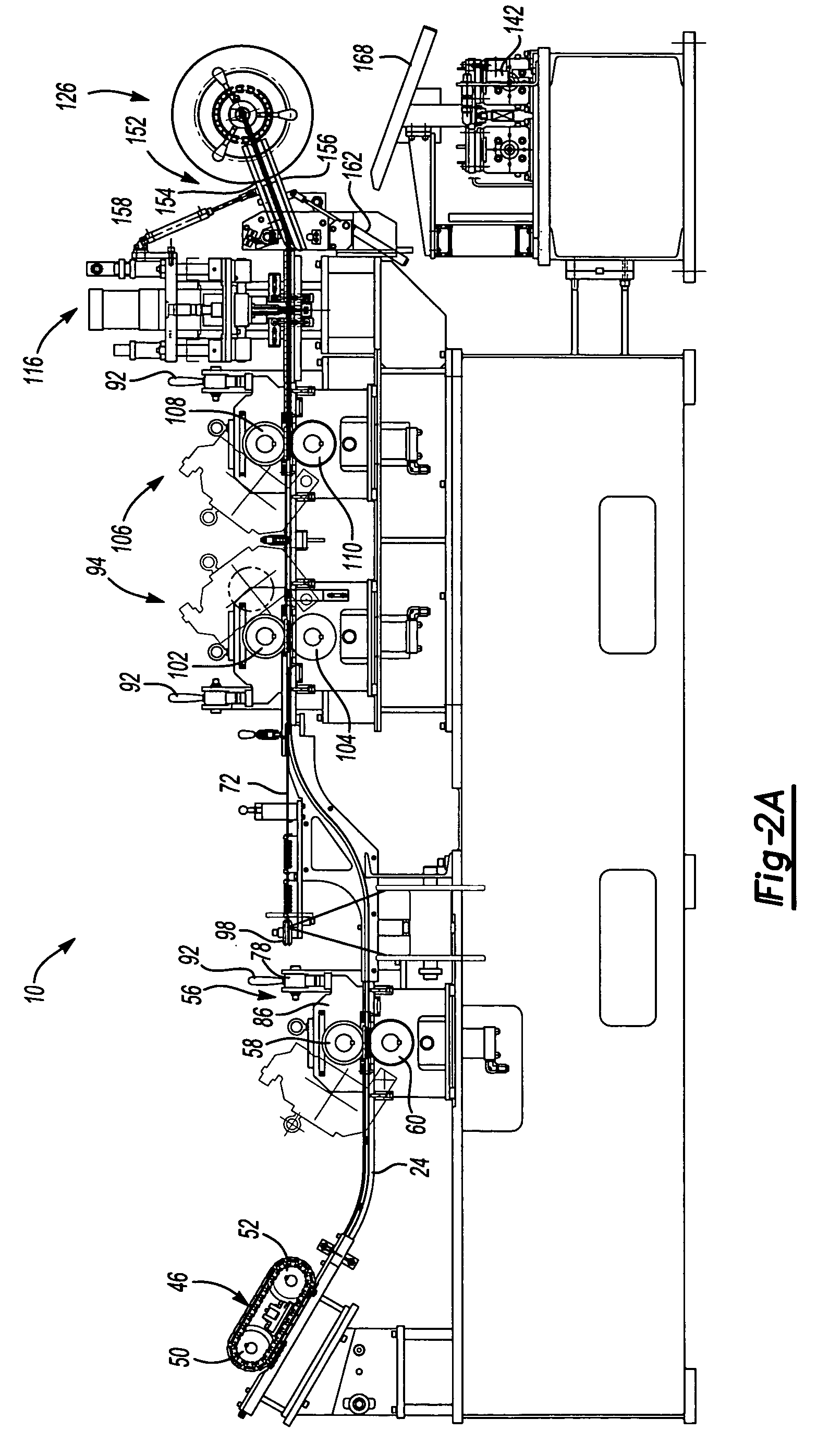
[0038] Preferably, the rod 14 has been preformed with at least one, and more preferably two wire grooves 18 and at least one, and preferably opposing re-entrant grooves 20 as is best represented by the cross-sectional view of the pierce nut 12 shown in FIG. 8, the purpose of which will be more evident and explained further below. In the preferred embodiment, a die press 22 receives the rod 14 to pierce and cut individual pierce nuts 12. The individual pierce nuts 12 are transferred from the die press 22 through a continuous ...


PUM


Abstract

An assembly line for continuously manufacturing fasteners from a rod with a groove for receiving a wire for retaining the fasteners in a strip includes a receiver for receiving the rod. A die press is arranged to receive the rod from the receiver and includes a piercing member for piercing an aperture in each fastener and a cutting member for cutting each fastener from the rod. A tapping member provides ribs to an inner wall of the aperture formed in the fastener by the piercing member. An inspector inspects the internal rib formed into the inner wall of the aperture disposed in the fastener verifying exactness of the aperture and the rib. A wire inserter inserts the wire into the groove forming a strip of connected fasteners. The inserter receives the fasteners sequentially from the inspector after verification of the exactness of the aperture disposed in each fastener.

Description

FIELD OF THE INVENTION [0001] The present invention is generally toward an approved method and apparatus of manufacturing fasteners. More specifically, the present invention is rated toward a method and apparatus of manufacturing fasteners in a continuous manner providing a strip of fasteners, which may be rolled into a coil for use at an installation site. BACKGROUND OF THE INVENTION [0002] Various methods of manufacturing fasteners, such as, for example, pierce nuts and the like have been used in the past and have provided satisfactory results enabling production of these types of fasteners in high volumes. End users of these pierce nuts have preferred using a continuous strip of pierce nuts connected side to side with a wire such as is disclosed in U.S. Pat. No. 3,845,860, for Fastener Strip. [0003] The installation of the pierce nuts is greatly simplified when provided to an end user in a continuous strip wound in a coil, which eliminates the need for expensive bowl mixers and a...

Claims


Application Information

Patent Timeline
IPC IPC(8): B21K1/64
CPCB21K1/66B21H8/00
Inventor VRANA, JOHN J.LADOUCEUR, HAROLD A.WARD, RICHARD P.GONZALES, JORGE
Owner WHITESELL FORMED COMPONENTS
Why Eureka
Try Eureka