Electric connector for shielded cable, a connector body thereof and a method of producing the electric connector

a shielded cable and electric connector technology, applied in the direction of securing/insulating coupling contact members, connection contact members, coupling device connections, etc., can solve the problems of affecting the transmission speed of signals, and adding a soldering process

Inactive Publication Date: 2003-11-25
JST MFG CO LTD
View PDF9 Cites 70 Cited by
  • Summary
  • Abstract
  • Description
  • Claims
  • Application Information

AI Technical Summary

Benefits of technology

In this electric connector for shielded cable, as the second housing is molded secondarily on the ground terminal, the ground terminal is made to contact hard the external conductor and the reliability of connection between them is improved, and in turn, more stable impedance characteristics are obtained. The signal line of the shielded cable is crimped in the barrel of the signal terminal, the ground line of the shielded cable is crimped in the barrel of the ground terminal, and the ground terminal is made to contact the support protrusion of the external conductor. As a result, there is no soldering process, and the work processes are reduced and the producibility is enhanced, and moreover, the impedance characteristics of the products are equalized. Furthermore, as the major parts are formed by overlaying the plate-shaped external conductor, the first housing, the signal terminal and the ground terminal, and the second housing, the electric connector can be made thinner.
When the second housing is molded secondarily, as the core pin presses the ground terminal against the support protrusion at the position of the through hole, the ground terminal will not be shifted or deformed under the pressure of the insulating material being secondarily molded, and the insulating material will not penetrate between the ground terminal and the support protrusion. Hence the secondary molding is effectively prevented from causing any defective connection between the ground terminal and the external conductor.
Accordingly, in the electric connector for connecting a shielded cable according to the present invention, as the second housing is molded secondarily, the ground terminal is made to contact hard the external conductor and the reliability of connection between them is improved and more stable impedance characteristics are obtained, and this allows, for example, stable high-speed transmission of signals. In this case, as the ground terminal is pressed by the core pin, the ground terminal is effectively prevented from being shifted or deformed and the insulating material is effectively prevented from penetrating between the ground terminal and the support protrusion to cause any defective connection between the ground terminal and the external conductor. Moreover, as there is no soldering process, the producibility is enhanced through reduction in the work processes and the impedance characteristics of the products are equalized. Furthermore, the electric connector can be made thinner, and this is desirable when such electric connectors are used in layers.

Problems solved by technology

These conventional electric connectors have problems that, as the ground terminal and the external conductor are connected together by making them contact each other, if the contact between them become unstable due to some causes such as vibration, the impedance characteristics will fluctuate and prevent, for example, stable high-speed transmission of signals.
However, it will add a soldering process and complicate the wire connection work.
Moreover, as it is difficult to keep the quantity of the solder at a constant level, it will impose a new problem that the impedance characteristics will vary from product to product.
This problem is also encountered when connection between a terminal and a shielded cable is made by soldering.

Method used


Image

  • Electric connector for shielded cable, a connector body thereof and a method of producing the electric connector
  • Electric connector for shielded cable, a connector body thereof and a method of producing the electric connector
  • Electric connector for shielded cable, a connector body thereof and a method of producing the electric connector

Examples


Embodiment Construction

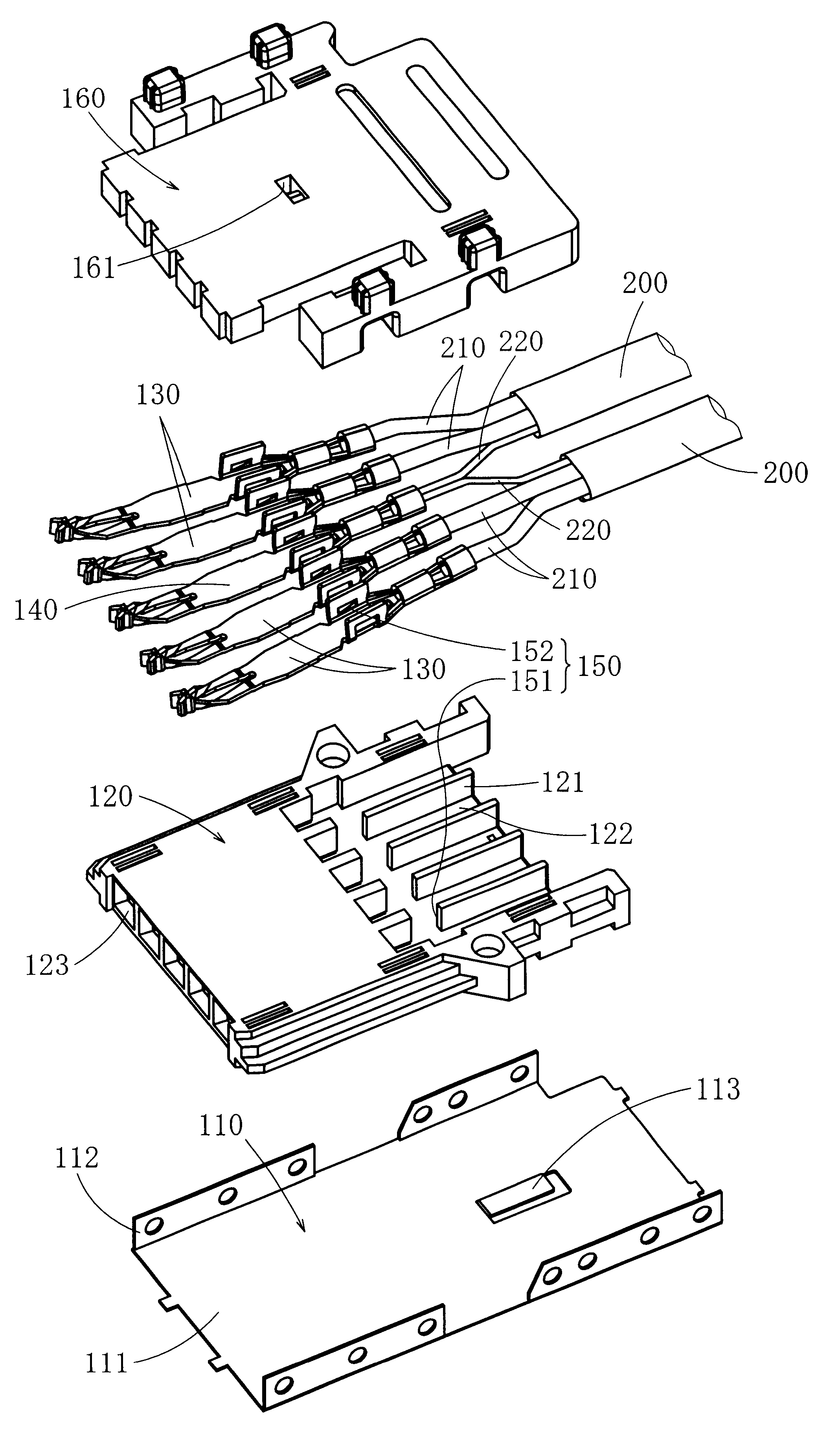
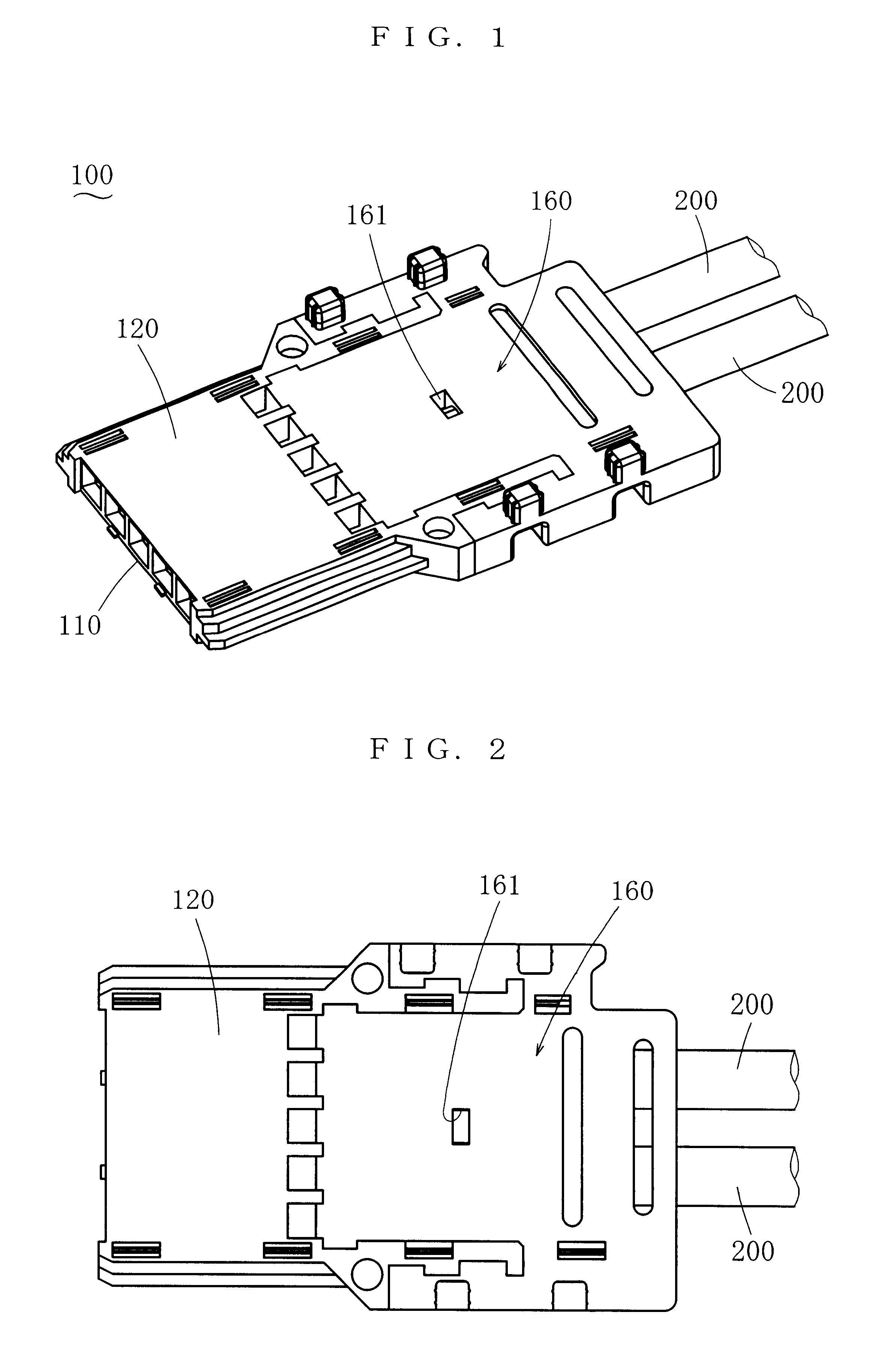
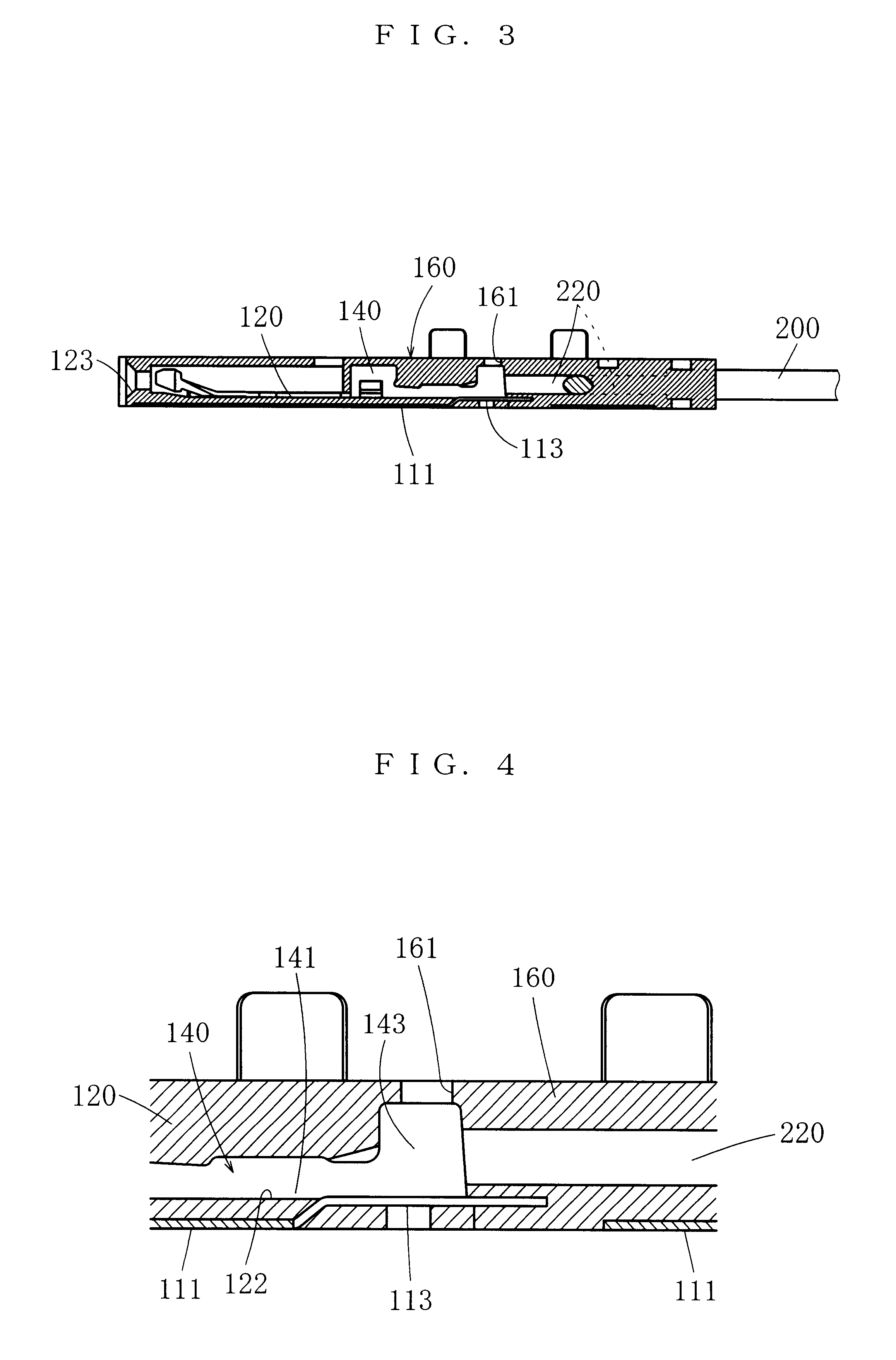
In the following, some embodiments of the present invention will be described. FIG. 1 through FIG. 5 show the first embodiment of the electric connector for shielded cable. This electric connector is provided with five female terminals and two shielded cables are connected to it. Each of these female terminals is to be connected to a counterpart male terminal that is mounted on a printed circuit board. The electric connector is used to transmit signals of computers. The first embodiment, however, merely exemplifies a preferred embodiment, and the number of poles of the electric connector according to the present invention, kind and number of shielded cables to be connected, application, form of counterpart terminals, etc. are not limited in any way by the first embodiment. The terminals of the electric connector according to the present invention may be male terminals. A shielded cable has at least one signal line and at least one ground line, and these lines are contained together ...


PUM


Abstract

An electric connector for shielded cable, which improves the reliability of connection between a ground terminal and an external conductor and secures stable impedance characteristics. In this electric connector, a first housing is primarily molded on the external conductor, the external conductor is provided with a support protrusion that protrudes inside of the external conductor and contacts the ground terminal, and the second housing being secondarily molded is provided with a through hole, which is formed by a core pin that protrudes inwards from a mold and presses the ground terminal at a position where the second housing faces the support protrusion with the ground terminal in between.

Description

1. Field of the InventionThe present invention belongs to a field of electric connectors that are used to connect shielded cables having both a signal line and a ground line and enable, depending on applications, high-speed transmission of signals. The present invention relates to an electric connector having a conductive plate-shaped external conductor to which a ground terminal is grounded, and relates to an electric connector wherein the reliability of connection between a ground terminal and an external conductor is improved and its producibility is enhanced.2. Related ArtElectric connectors for shielded cable are known, which comprise a conductive tubular external conductor, an insulating housing being contained inside the external conductor, and a signal terminal and a ground terminal both being contained inside the housing, and wherein the signal terminal is to be connected to a signal line of the shielded cable and the ground terminal is to be connected to a ground line ther...

Claims


Application Information

Patent Timeline
Patent Type & Authority Patents(United States)
IPC IPC(8): H01R13/40H01R13/405H01R43/24H01R4/10H01R13/648H01R4/18H01R43/20H01R13/652H01R13/658H01R13/6581H01R43/00
CPCH01R4/185H01R43/24H01R13/648H01R13/405H01R13/652
Inventor KURODA, KEIJIHORIUCHI, HIDEAKI
Owner JST MFG CO LTD
Why Eureka
Try Eureka