Low-power output controlled circuit

a low-power output and control circuit technology, applied in logic circuits, oscillator generators, pulse techniques, etc., can solve the problems of low-power environment relevance, large dc switching current (magnitude), and existing technologies' attempts to implement output control. achieve the effect of low-power design and large consumption

Inactive Publication Date: 2003-11-25
MICROCHIP TECH INC
View PDF13 Cites 44 Cited by
  • Summary
  • Abstract
  • Description
  • Claims
  • Application Information

AI Technical Summary

Benefits of technology

An advantage of the present invention is that it requires few components, none of which consume much power. Another advantage is that the method of slew-rate control presented in this invention uses feedback to regulate the slew rate of the output stage. Thus, the slew-rate control method is more precise and consistent than existing technologies' methods, and is applicable to very low power circuits.
is that it requires few components, none of which consume much power. Another advantage is that the method of slew-rate control presented in this invention uses feedback to regulate the slew rate of the output stage. Thus, the slew-rate control method is more precise and consistent than existing technologies' methods, and is applicable to very low power circuits.
A further advantage of the present invention is that it conducts substantially no crow-bar current and minimal switching current, essential aspects for very low power design.

Problems solved by technology

In low-power applications, the DC switching current is conducted for an especially long period of time, because of the slow propagation delay of an output state change.
Also because the comparator has a large output driver to drive a large load, the DC switching current (magnitude) can become quite large.
Existing technologies' attempts to implement output control have not offered solutions relevant to the very low-power environment.
However, these circuits fail to address the problems of excessive power consumption and slew rate.
Other existing technologies' output control circuits are slew-rate-limited, but not very low-power.
A strongly-switching output driver is disadvantageous for very low power applications because of the high slew rate.
A high slew rate of the output driver may cause an increase in the total current used in the system because it may lead to ground or supply bounce, and charge / discharge of V.sub.dd -V.sub.ss capacitance either on or off chip, e.g., decoupling capacitors.
A high slew rate output driver may also couple noise into sensitive high impedance input nodes that may be present in very low power circuits.
However, existing technologies' low power drivers, which are slew-rate-limited, may be ineffective in a very-low-power application because, at least in part, their slew-rate control circuit does not use feedback to adjust itself to achieve optimal slew-rate.
None of the existing technologies' output control circuits substantially eliminate crow-bar current.

Method used


Image

  • Low-power output controlled circuit
  • Low-power output controlled circuit
  • Low-power output controlled circuit

Examples


Embodiment Construction

Referring now to the drawings, the details of exemplary embodiments of the present invention are schematically illustrated. Like elements in the drawing will be represented by like numbers, and similar elements will be represented by like numbers with a different lower case letter suffix.

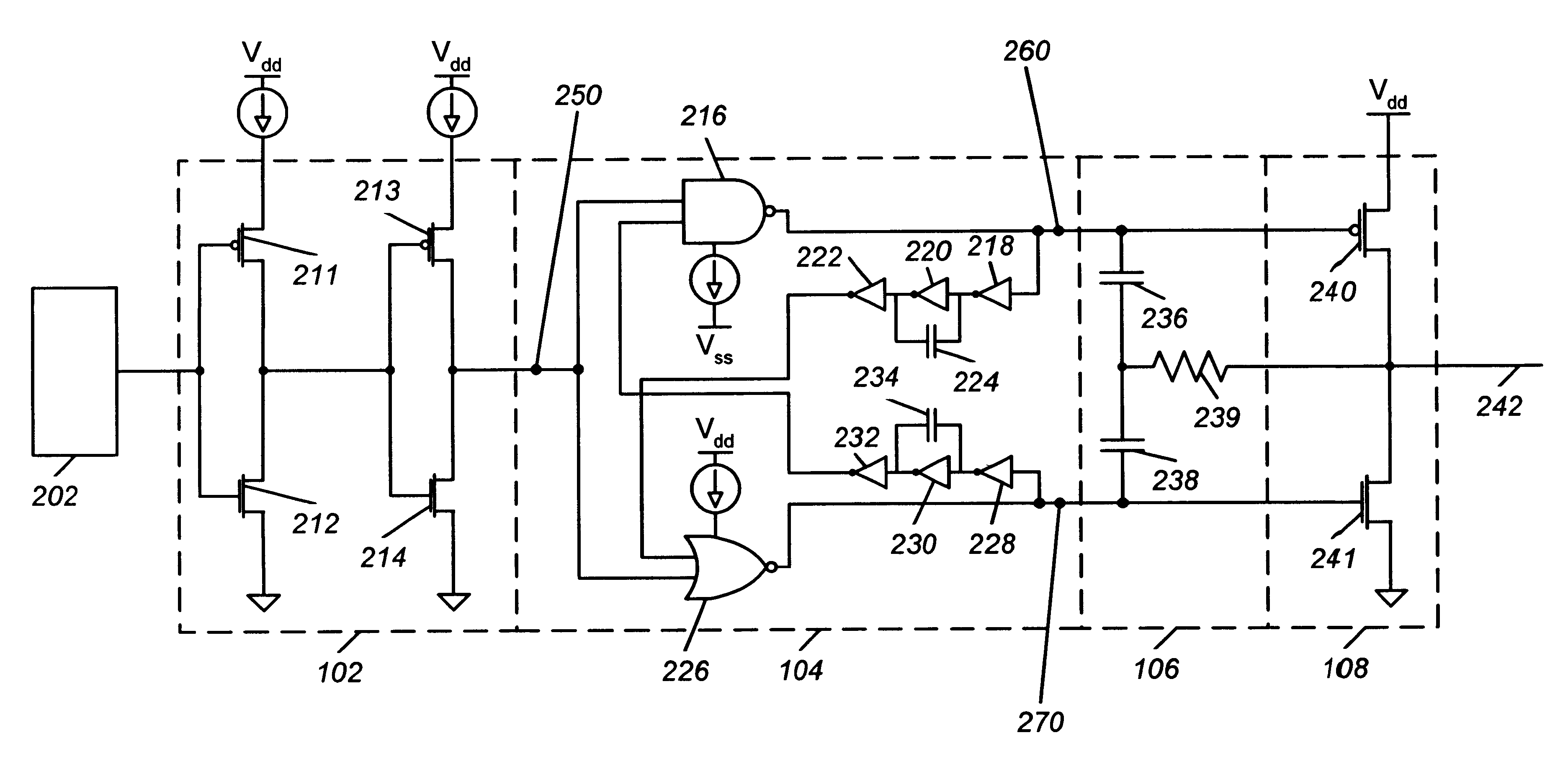
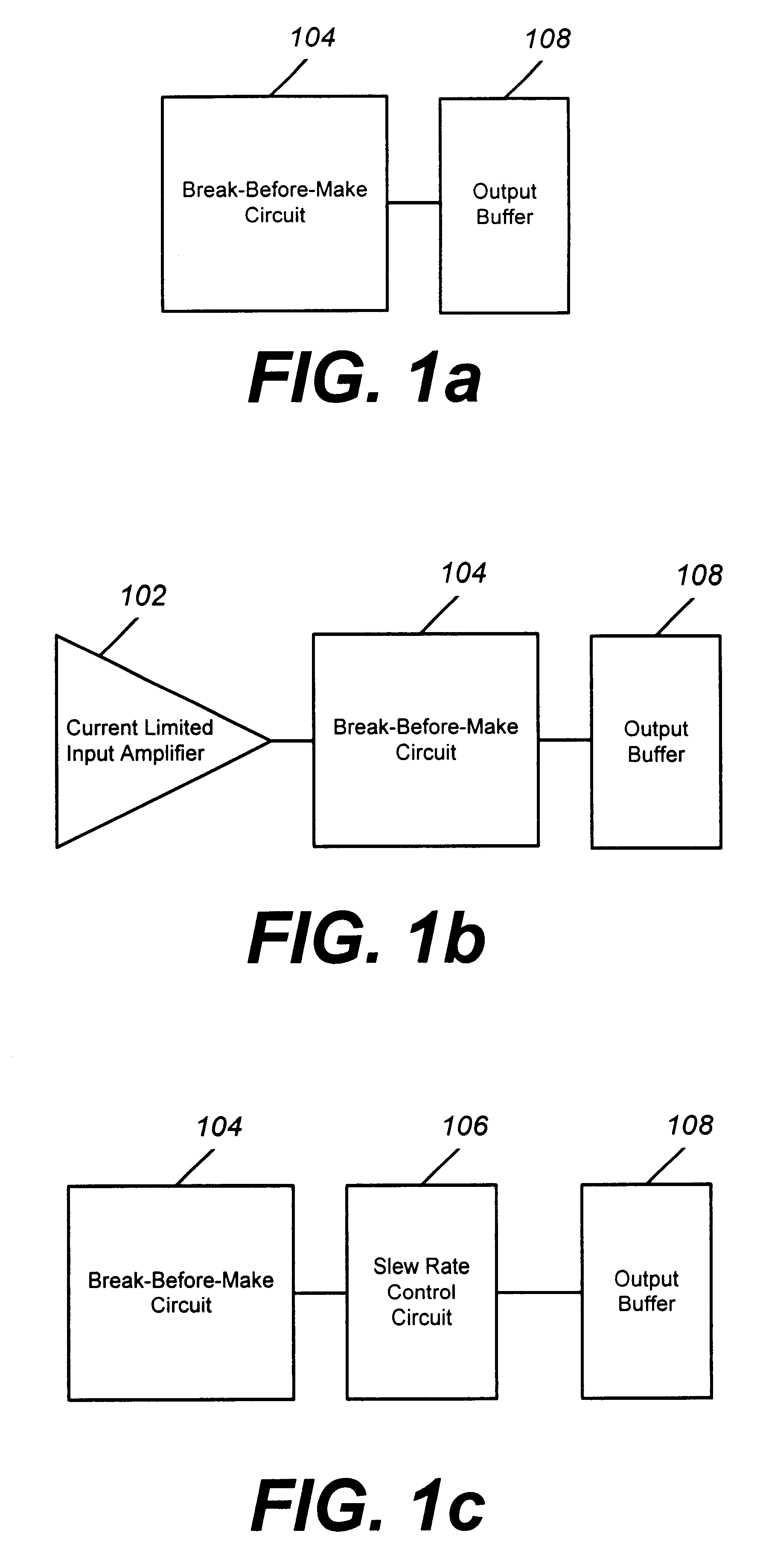
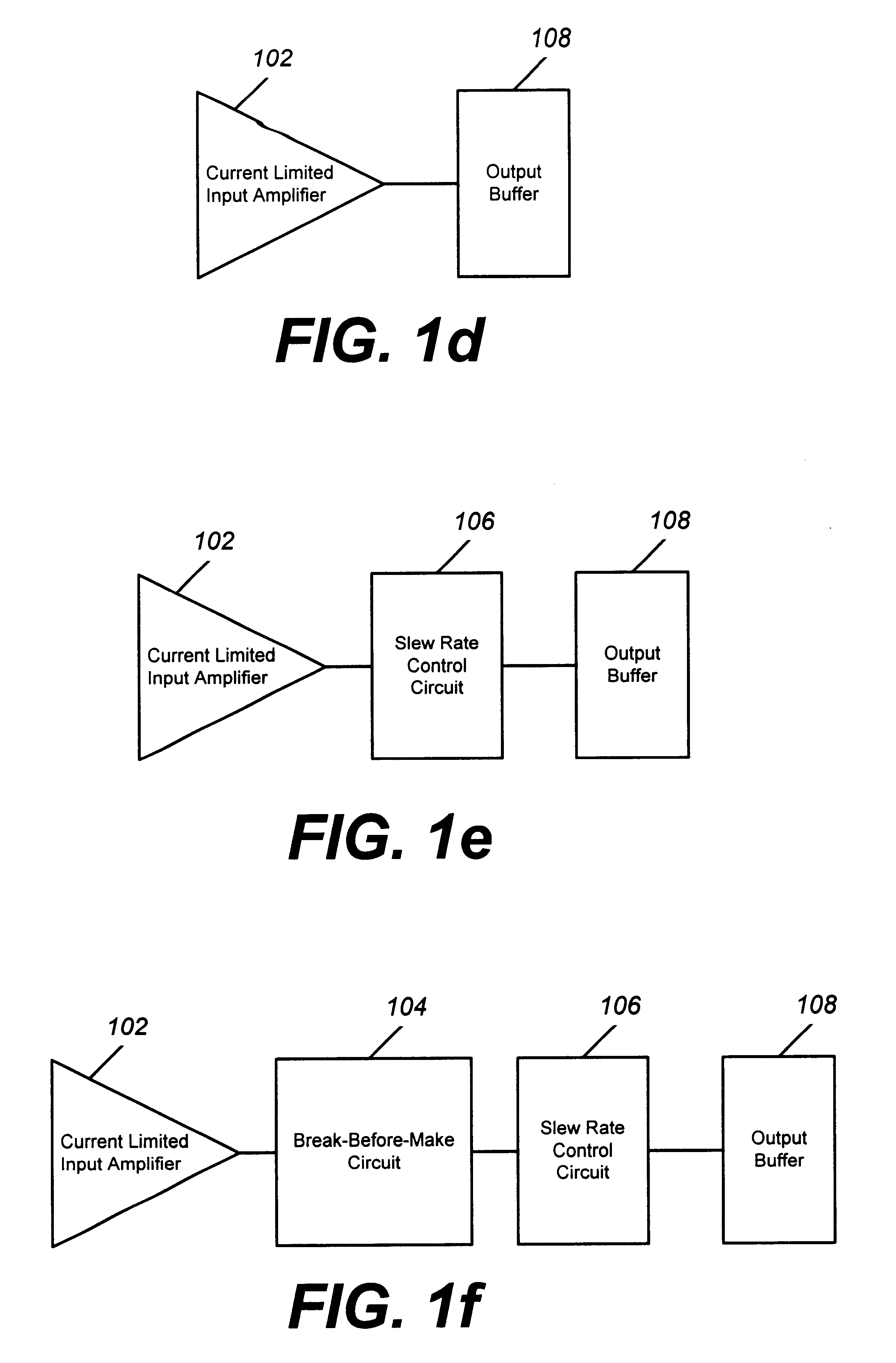
Referring to FIG. 1, illustrated are block diagrams of six exemplary embodiments of the present invention. In FIG. 1a, break-before-make circuit 104 is connected to output buffer 108. In FIG. 1b, current limited input amplifier 102 is connected to break-before-make circuit 104. Break-before-make circuit 104 is connected to output buffer 108. In FIG. 1c, slew rate control circuit 106 is connected between break-before-make circuit 104 and output buffer 108. In FIG. 1d, current limited input amplifier 102 is connected to output buffer 108. In FIG. 1e, current limited input amplifier 102 is connected to slew rate control circuit 106. Slew rate control circuit 106 is connected to output buffer 108. In FI...


PUM


Abstract

An output buffer, a slew-rate control circuit, a break-before-make circuit, and a current limited input amplifier are connected as a digital output driver. This provides a simple apparatus and method of switching current control and slew-rate control that limits power consumption of the digital output driver. To further minimize switching current, capacitors may be added to the break-before-make circuit. A comparator input circuit may be connected to the current limited input amplifier to form a comparator having a low-power-consuming digital output.

Description

The present invention relates generally to output circuits, and more particularly to a method and apparatus for a comparator output controlled circuit.BACKGROUND OF THE INVENTION TECHNOLOGYA comparator is a circuit that senses the difference between its two inputs and changes its output state depending on which of the inputs is higher in voltage. In CMOS (Complementary Metal Oxide Semiconductor) technology, as the comparator output makes a transition, there is current that flows for a short time when both NMOS (Negative Channel MOS) and PMOS (Positive Channel MOS) transistors are on. During a change in output state, a comparator, or any other analog or digital circuit, may conduct significant current from the power source.Electronic circuits are being pressed into operation at lower supply voltages and currents. For some very low power comparators, the switching or transition current may be large relative to the static quiescent current of the comparator. In low-power applications, ...

Claims


Application Information

Patent Timeline
Patent Type & Authority Patents(United States)
IPC IPC(8): H03K19/00
CPCH03K19/0013
Inventor NOLAN, JAMES B.
Owner MICROCHIP TECH INC
Why Eureka
Try Eureka