
Cone with torque transmitting members for continuous variable transmissions

a technology of transmission member and transmission member, applied in the direction of gearing, gearing elements, hoisting equipment, etc., can solve the problems of only transmitting torque by friction, wasting relative large torque, wear and frictional energy loss,

Inactive Publication Date: 2003-12-02
TAY ARMIN SEBASTIAN
View PDF10 Cites 19 Cited by
  • Summary
  • Abstract
  • Description
  • Claims
  • Application Information

AI Technical Summary

Problems solved by technology

Here a relatively large torque would be wasteful.
One problem with this CVT is that changing the transmission ratio causes wear and frictional energy loses, since the belt has to slide and / or stretch relative to the surfaces of the cones as the pitch diameter is changed.
Another problem with the CVT mentioned in the previous paragraph is that torque can only be transmitted by friction.

Method used


Image

  • Cone with torque transmitting members for continuous variable transmissions
  • Cone with torque transmitting members for continuous variable transmissions
  • Cone with torque transmitting members for continuous variable transmissions

Examples


Embodiment Construction

Preferred Embodiments

The inventor believes that there is no best method to utilize this invention. Here for some machines one variation, say variation A, works better than say variation B, but the opposite might also be true for some other machines. However, the inventor will clearly identify the advantages of one variation over the other.

First the basic idea of the invention will be presented in the General Cone Assembly section. Then some alternate configuration of the invention, labeled as cone assembly 26A, cone assembly 26B, and cone assembly 26C will be presented. Next, a mover mechanism will be described. Finally, several preferred configurations for a Continuous Variable Transmission (CVT) utilizing the invention will be described.

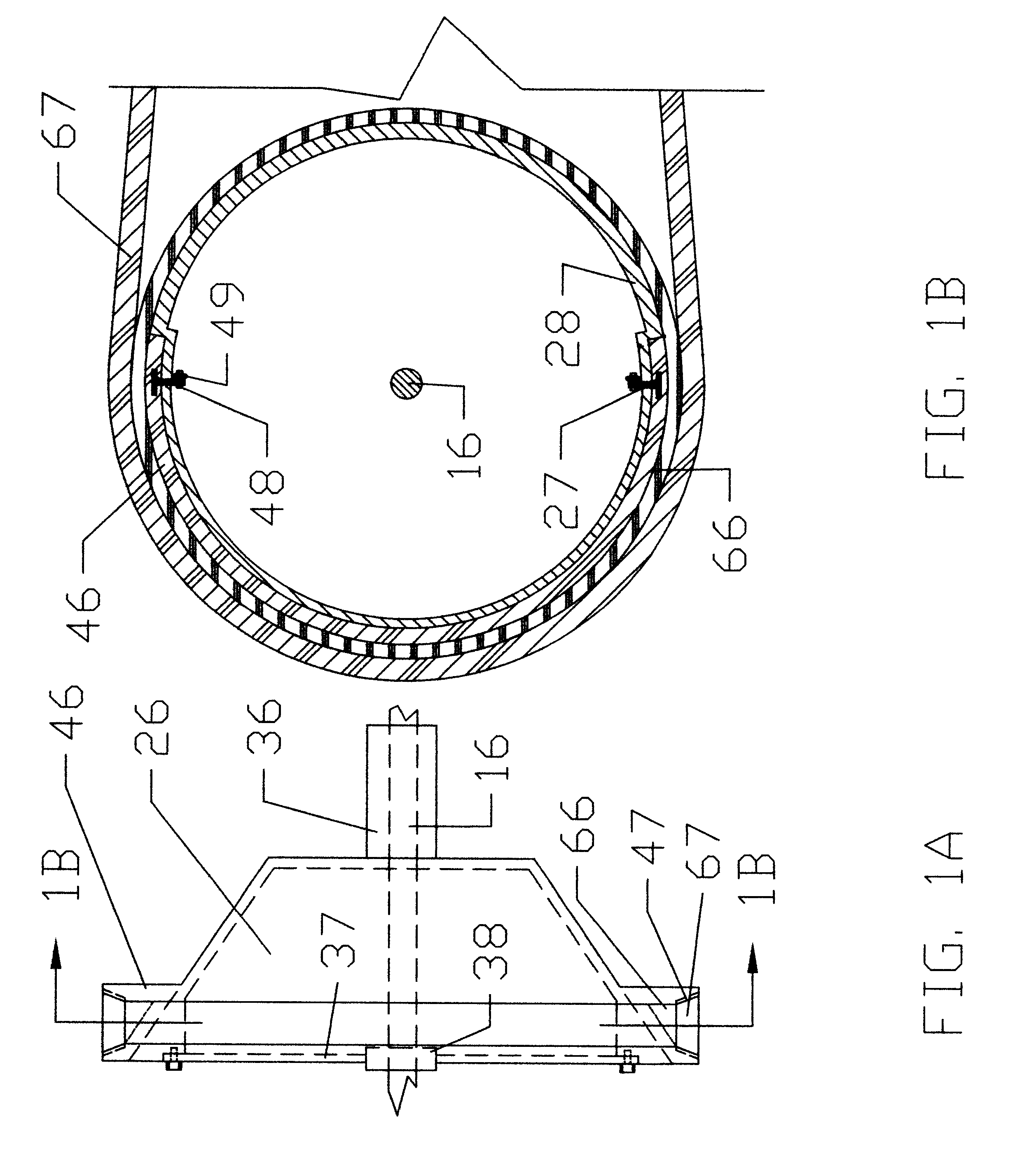
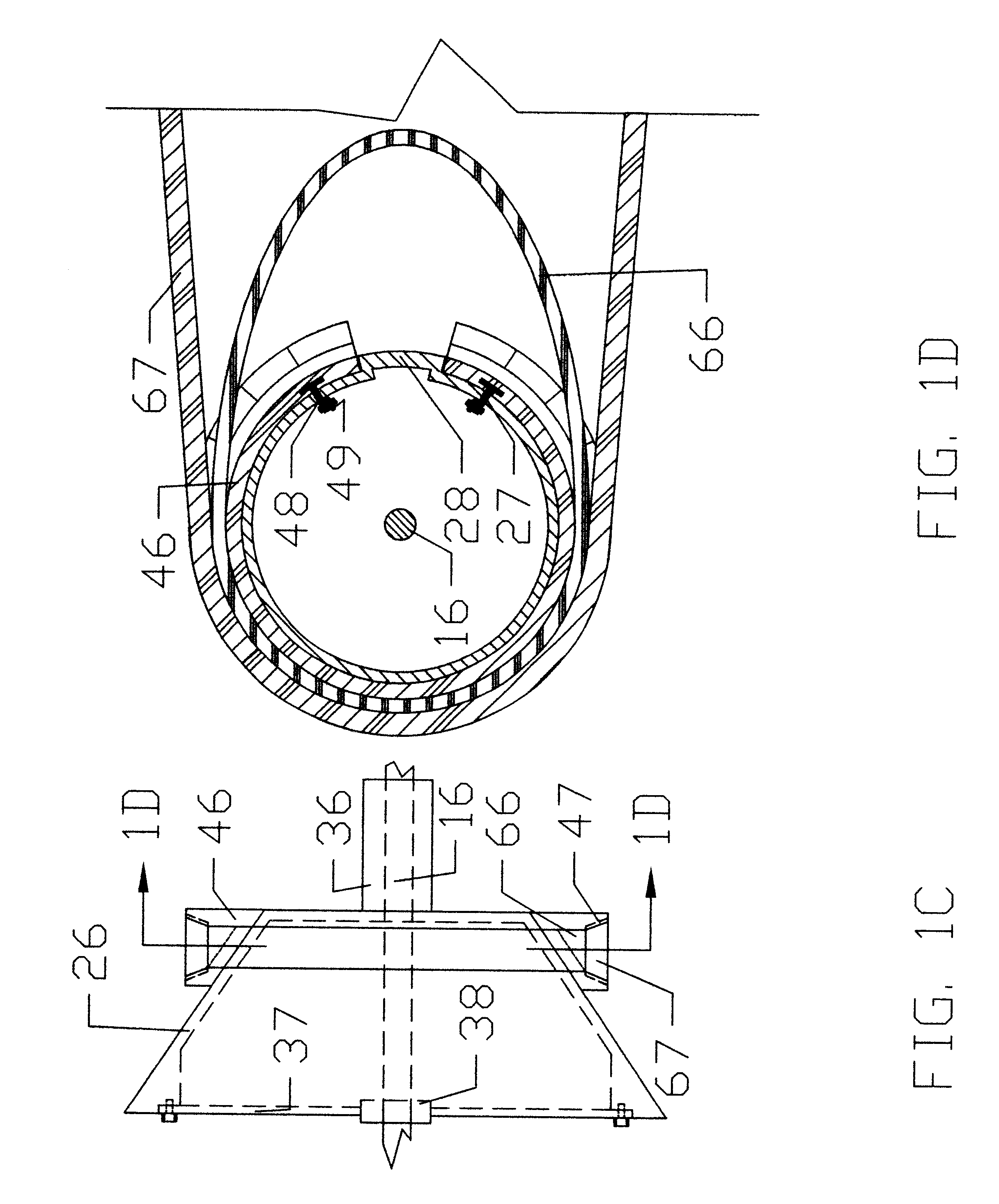
General Cone Assembly (Cone Assembly 26)--FIGS. 1A, 1B, 1C, 1D

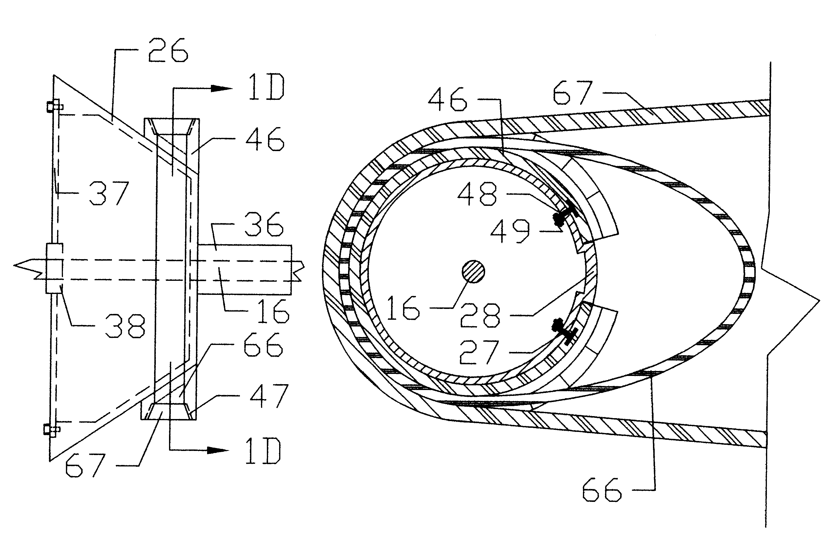
The corner stone of the invention is shown in FIGS. 1A, 1B, 1C, and 1D. It consists of a cone 24, which is keyed to a shaft 16, on which one torque transmitting member 46 is attached as ...


PUM


Abstract

A cone to which one or several torque transmitting member(s) are attached as to form at least one torque transmitting arc on the surface of the cone. The torque transmitting member(s) will be used for torque transmission between at least one rotational energy conveying device and the cone. The torque transmitting member(s) are attached in a manner such that significant circumferential sliding that occurs between the torque transmitting surface(s) of the torque transmitting member(s) and the torque transmitting surface(s) of the rotational energy conveying device(s) when the pitch diameter of the torque transmitting member(s) is changed can be eliminated, such that wear and frictional energy losses are significantly reduced, and positive engagement devices, such as teeth, can be used for torque transmission between the torque transmitting member(s) and the rotational energy conveying device(s). The cone with torque transmitting member(s) can be used to construct various Continuous Variable Transmissions that have a long life, low frictional energy losses, and can be made non-friction dependent.

Description

1. Field of the InventionThis invention relates to variable torque / speed transmission, specifically to a variable transmission where the transmission ratio can be varied continuously between any two predetermined values.2. Description of Prior ArtIn most applications the transmission ratio, which is the torque vs. speed ratio transmitted by a driving source, needs to be adjustable in order for the driving source to operate efficiently and effectively. For example, for a vehicle, during start-up, assuming that it is on a level road, the driving source needs to provide torque to accelerate the vehicle and torque to overcome the resisting forces mainly due to friction and wind resistance. Once the vehicle has reached its desired speed, again assuming that it is on level road, the engine only needs to provide torque to overcome the resisting forces, which in this case is likely to be greater than during start-up, but less than the total torque needed during start-up. Hence in this case ...

Claims


Application Information

Patent Timeline
Patent Type & Authority Patents(United States)
IPC IPC(8): F16H55/54F16H9/02F16H9/10F16H55/32F16H9/24
CPCF16H9/10F16H55/54F16H9/24
Inventor TAY, ARMIN SEBASTIAN
Owner TAY ARMIN SEBASTIAN
Learn More