Tissue manipulation

Inactive Publication Date: 2003-12-02
HAYHURST JOHN O
View PDF43 Cites 480 Cited by
  • Summary
  • Abstract
  • Description
  • Claims
  • Application Information

AI Technical Summary

Benefits of technology

With the anchor member anchored in the hole, the suture is available for securing the tissue to the bone. One way of using the suture to secure the tissue to the bone is to attach a retainer to the suture for pressing the tissue against the bone. The retainer includes resilient suture-engaging edges and corners, and is slidable along the suture in one direction, bu

Problems solved by technology

Conventional medical clamps have certain disadvantages when used for manipulating cartilage or other tissue within a joint during arthroscopic surgery.
Primarily, the clamps have a tendency to slip off the cartilage.
Additionally, the size of the clamps in relation to the relatively small space within the joint makes it difficult to maneuver other surgical instruments, such as a scalpel or arthroscope, within the confined space of the joint.
Such clamps can also interfere with the view of the inside of the joint afforded by the arthroscope.
Since the clamps must be .introduced into the joint through an incision, they are limited in their range of manipulation by

Method used


Image

  • Tissue manipulation
  • Tissue manipulation
  • Tissue manipulation

Examples


Embodiment Construction

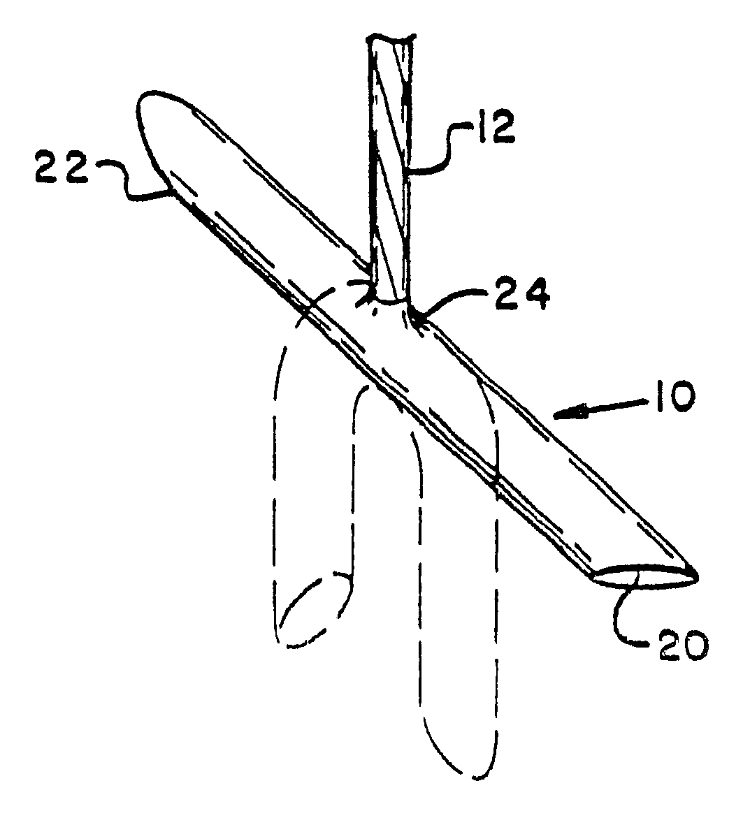
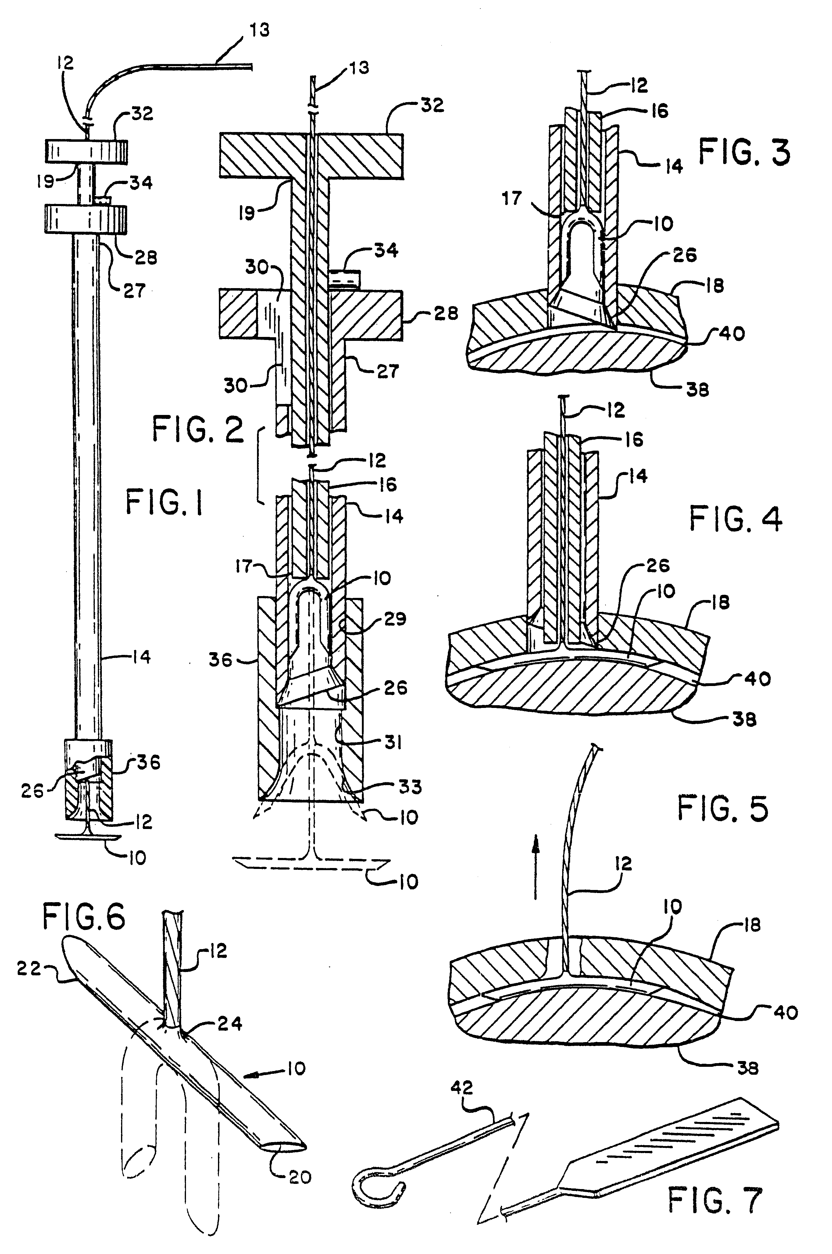
One preferred embodiment of the present invention, shown assembled in FIGS. 1 and 2, provides a resiliently deformable anchor member 10, which is attached to a suture 12 and adapted to fit deformably within the tip 26 of a hollow needle 14. A hollow tube 16, also adapted to fit within the needle 14, is used to expel the anchor member from the tip 26 of the needle after the needle has pierced a piece of fibrous tissue, such as the cartilage 18, as shown in FIGS. 3 and 4. Once expelled between the cartilage 18 and bone 38, the anchor member resiliently resumes its normal shape, as shown in FIG. 5. The anchor member of the invention might also be used to secure ligament or tendon, as will be described hereinafter, and the term tissue will be broadly used herein to encompass cartilage, tendons, ligaments and similar tissue.

The anchor member 10, shown in perspective view in FIG. 6, is an elongated cylindrical member. The anchor member 10 has end faces 20 and 22,at the respective extremit...


PUM


Abstract

An apparatus and method for manipulating and anchoring tissue is provided. The invention is directed to solving the problem of manipulating and anchoring tissue within a joint when access to that tissue is limited, for example, during arthroscopic surgery.

Description

TECHNICAL FILEDThis invention relates to an apparatus and method for manipulating and anchoring cartilage and similar fibrous tissue within a joint.Conventional medical clamps have certain disadvantages when used for manipulating cartilage or other tissue within a joint during arthroscopic surgery. Primarily, the clamps have a tendency to slip off the cartilage. Additionally, the size of the clamps in relation to the relatively small space within the joint makes it difficult to maneuver other surgical instruments, such as a scalpel or arthroscope, within the confined space of the joint. Such clamps can also interfere with the view of the inside of the joint afforded by the arthroscope. Since the clamps must be .introduced into the joint through an incision, they are limited in their range of manipulation by the location of the incision. In order to apply a desired directional traction to the cartilage, it may be necessary to release the clamp from the cartilage, reintroduce the clam...

Claims


Application Information

Patent Timeline
IPC IPC(8): A61F2/08A61B17/04A61B17/00
CPCA61B17/0401A61F2/0811A61B2017/00004A61B2017/0404A61B2017/0409A61F2002/0888A61B2017/0451A61B2017/0464A61B2017/0417
Inventor HAYHURST, JOHN O.
Owner HAYHURST JOHN O
Why Eureka
Try Eureka