
High efficiency ceiling fan blades

a ceiling fan and high-efficiency technology, applied in lighting and heating apparatus, ventilation systems, heating types, etc., can solve the problems of flat ceiling fan blades, excessive noise that is noticeable to persons, and none of these propellers are designed for optimum airflow

Inactive Publication Date: 2003-12-09
UNIV OF CENT FLORIDA ADM 243
View PDF35 Cites 65 Cited by
  • Summary
  • Abstract
  • Description
  • Claims
  • Application Information

AI Technical Summary

Problems solved by technology

These patents while moving air are not concerned with maximizing optimum downward airflow.
Furthermore, many of the flat ceiling fan blades have problems such as vibrations and wobbling during use, and excessive noise that is noticeable to persons in the vicinity of the fan blades.
None of these propellers are designed for optimum airflow at low speeds of less than approximately 200 rpm which is the desired speeds used in overhead ceiling fan systems.
Using two pieces for each blade adds extreme costs in both the manufacturing and assembly of the ceiling itself.
Furthermore, the grooved connection point in the Volk devices would appear to be susceptible to separating and causing a hazard to anyone or any property beneath the ceiling fan itself.
Such an added device also has necessarily less than optimal aerodynamic properties.
Clearly, such a blades would not be aesthetically pleasing to the user to have various holes and ribs visible on the blades, and there is no description for increasing airflow with such an arrangement.

Method used


Image

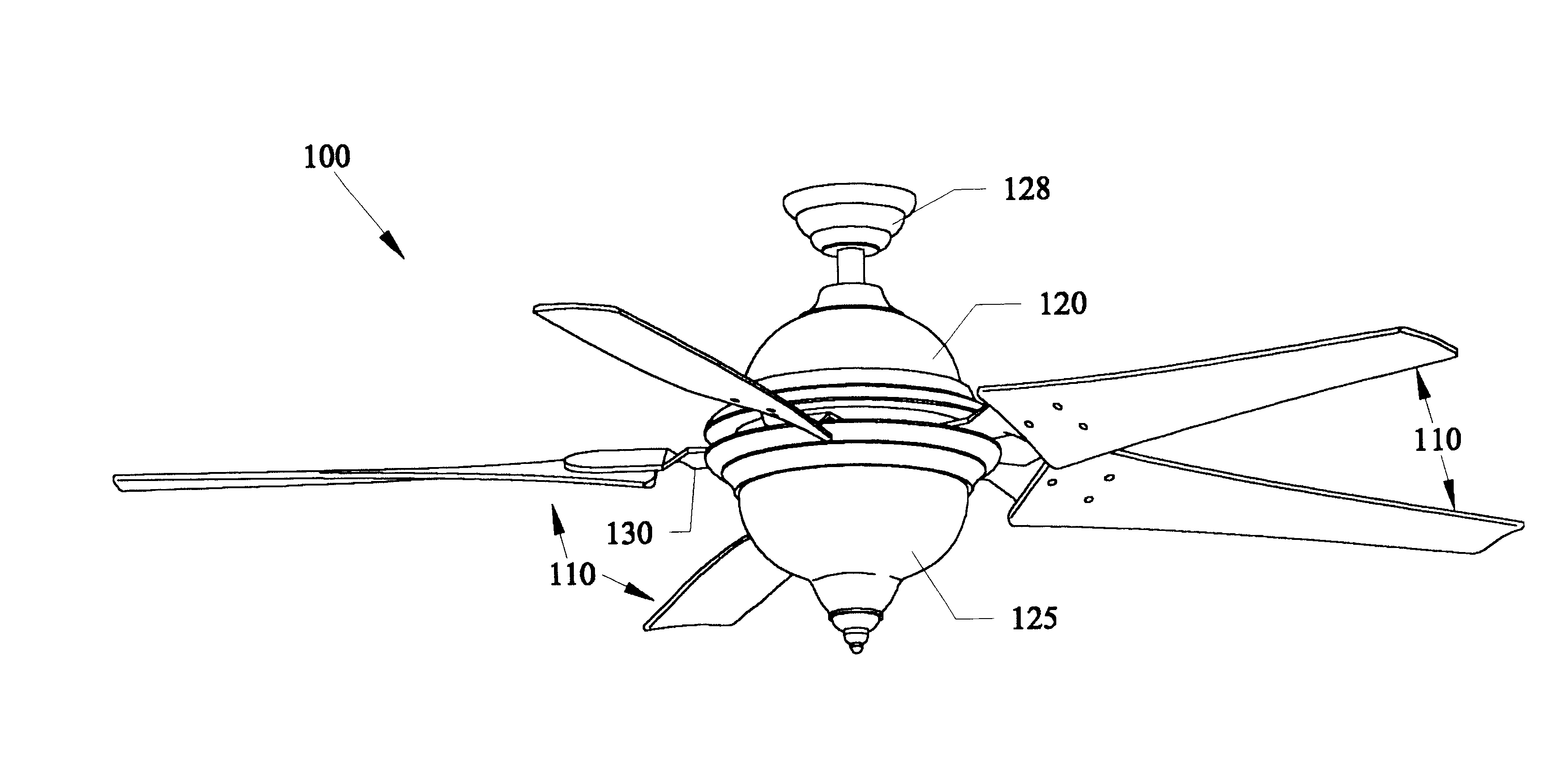
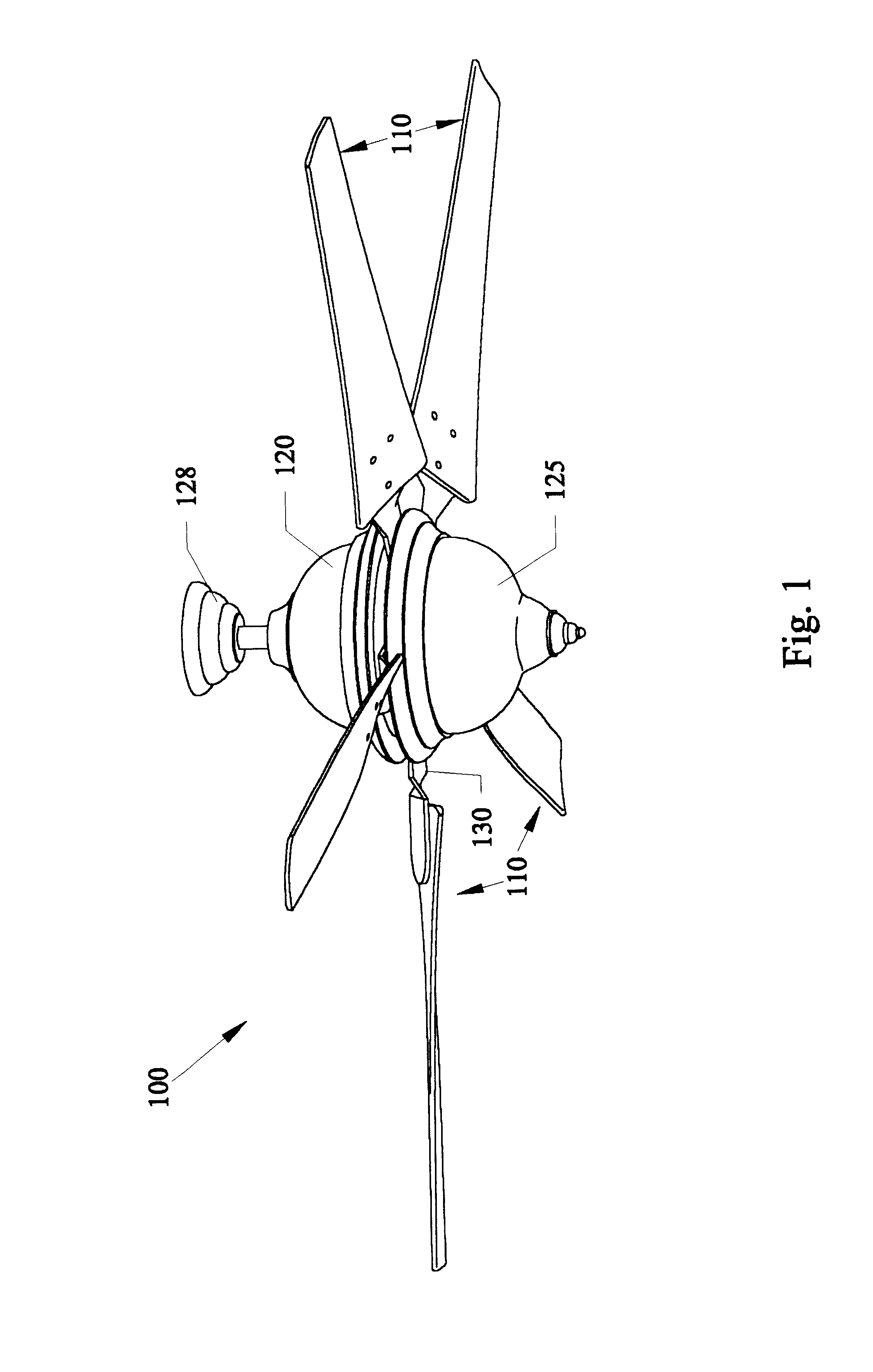
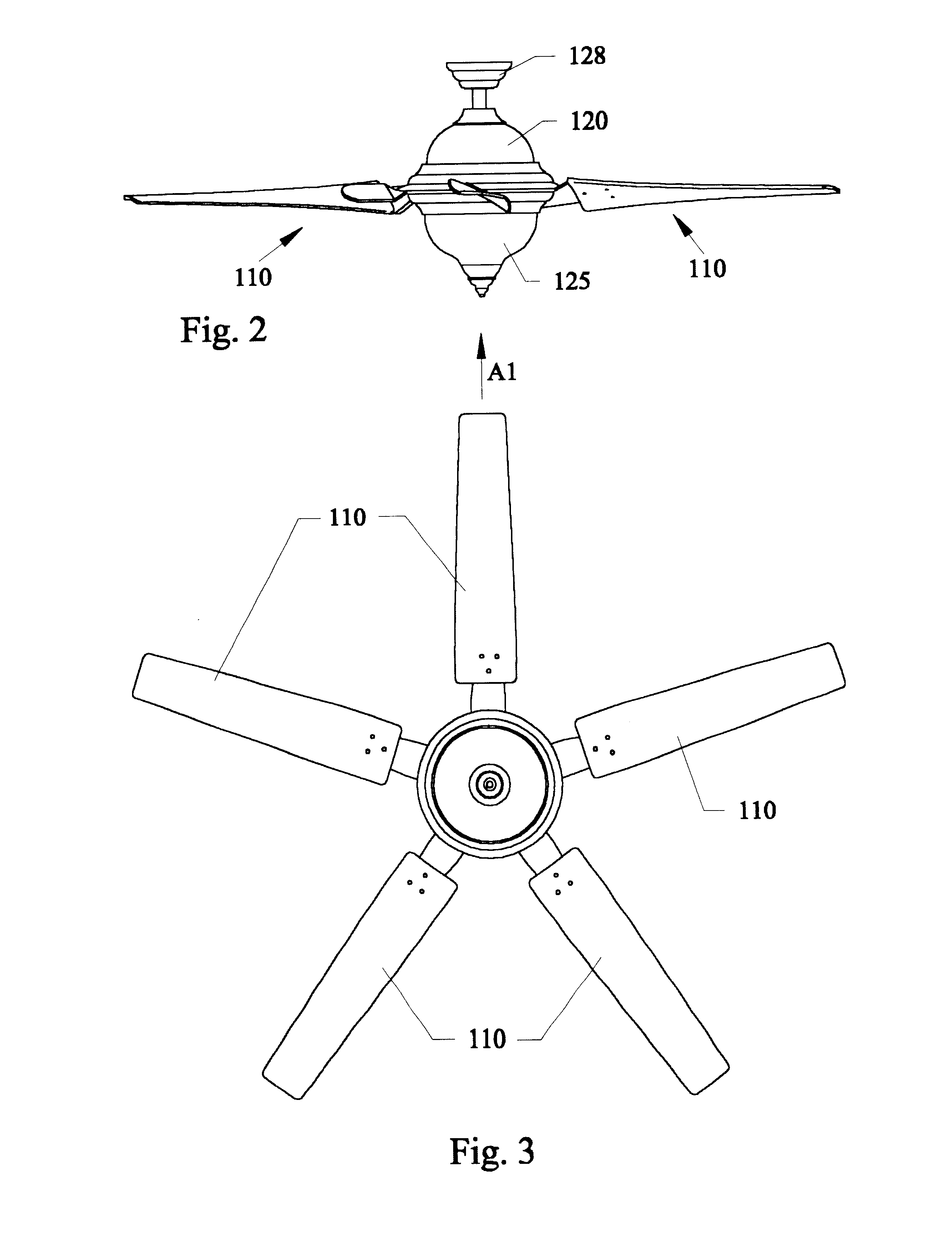
  • High efficiency ceiling fan blades
  • High efficiency ceiling fan blades
  • High efficiency ceiling fan blades

Examples


second embodiment

Subject invention second embodiment had an overall wing span of approximately 52", and used fan blades each being made of injection molded plastic.

Table 1 shows running the second embodiment of the subject invention at low speed operations, with the Power Drawer is the instantaneous electric power requirement in Watts. The parameters include power(in watts) and speed(revolutions per minute(rpm)).

Table 2 shows running the second embodiment of the subject invention at medium speed operations, with the Power Drawer is the instantaneous electric power requirement in Watts.

Table 3 shows running the second embodiment of the subject invention at high speed operations, with the Power Drawer is the instantaneous electric power requirement in Watts.

third embodiment

FIG. 15A is a perspective view of a single fan blade 310 of a third embodiment 300 of invention showing the single fan blade 310 having an overall length D3 between tip end 300TE and root end 300RE being approximately 23.5 inches, and various reference cross-sections(300RS(4), 300RE) being approximately 4.70 inches from one another along air foil center line 300ACL, and blade 310 having leading edge 300LE and trailing edge 300TEDGE oriented along the blade rotational plane RP. FIG. 15B is an end view of the single fan blade 310 of FIG. 15A representing degrees of twist between from the root end 300RE to the tip end 300TE, when the blade is positioned in a selected position on a ceiling fan motor assembly like those shown in the previous embodiments. The tip end 300TE has an angle of approximately 4.71 degrees from a horizontal plane that is parallel to the ceiling. In other words, the angle would be approximately 4.71 degrees from a motor axis(MA). The root end 200RE would have an a...


PUM


Abstract

Ceiling fan blades for maximizing air flow at operational speeds of up to approximately 200 revolutions per minute(rpm). The blades have a positive twist at the tip ends of approximately 5 degrees to approximately 10 degrees parallel to the ceiling. The root end of the blades closest to the motor can have a positive twist exceeding that of the tip end and can be approximately 20 to approximately 35 degrees parallel to the ceiling. The ceiling fans can have individual blade lengths of approximately 20 inches and overall spans of up to approximately 52 inches and up to approximately 54 inches. Each embodiment can use three, four, and five blades, with the blades being made of injection molded plastic. and the like. The embodiments can include built in light kit domes.

Description

BACKGROUND AND PRIOR ARTCeiling fans have been around for many years as a useful air circulator. The popular blade style over the years is a flat planar rectangular blade that can have a slight tilt, as shown for example in U.S. Pat. No. Des. 355,027 to Young and U.S. Pat. No. Des. 382,636 to Yang. These patents while moving air are not concerned with maximizing optimum downward airflow. Furthermore, many of the flat ceiling fan blades have problems such as vibrations and wobbling during use, and excessive noise that is noticeable to persons in the vicinity of the fan blades.Aircraft, marine and automobile engine propeller type blades have been altered over the years to shapes other than flat rectangular. See for example, U.S. Pat. No. 1,903,823 to Lougheed; U.S. Pat. No. 1,942,688 to Davis; U.S. Pat. No. 2,283,956 to Smith; U.S. Pat. No. 2,345,047 to Houghton; U.S. Pat. No. 2,450,440 to Mills; U.S. Pat. No. 4,197,057 to Hayashi; U.S. Pat. No. 4,325,675 to Gallot et al.; U.S. Pat. N...

Claims


Application Information

Patent Timeline
Patent Type & Authority Patents(United States)
IPC IPC(8): F04D25/08F04D27/00F04D25/02F24F11/00F24F7/007G05D23/19
CPCF04D25/088F04D27/00F24F7/007F24F11/0034Y02B30/746F24F11/0079F24F2011/0036F24F11/0012F24F11/30F24F2110/10F24F2120/10F24F2120/14F24F11/77F04D29/384Y02B30/70
Inventor PARKER, DANNY S.SU, GUAN HUAHIBBS, BART D.
Owner UNIV OF CENT FLORIDA ADM 243
Learn More