

Horn antenna for a radar device
a radar device and horn technology, applied in the direction of waveguide horns, protective materials radiating elements, instruments, etc., can solve the problems of inadequacies of metal antennas of the mentioned types, inability to manufacture them, and inability to meet the requirements of use, etc., to achieve the effect of simple and easy installation, simple sealing mechanism and high degree of automation
- Summary
- Abstract
- Description
- Claims
- Application Information
AI Technical Summary
Problems solved by technology
Method used
Image

Examples
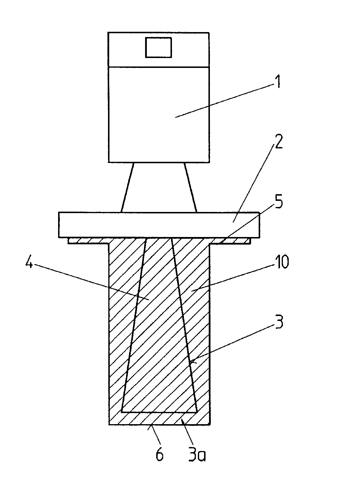
first embodiment
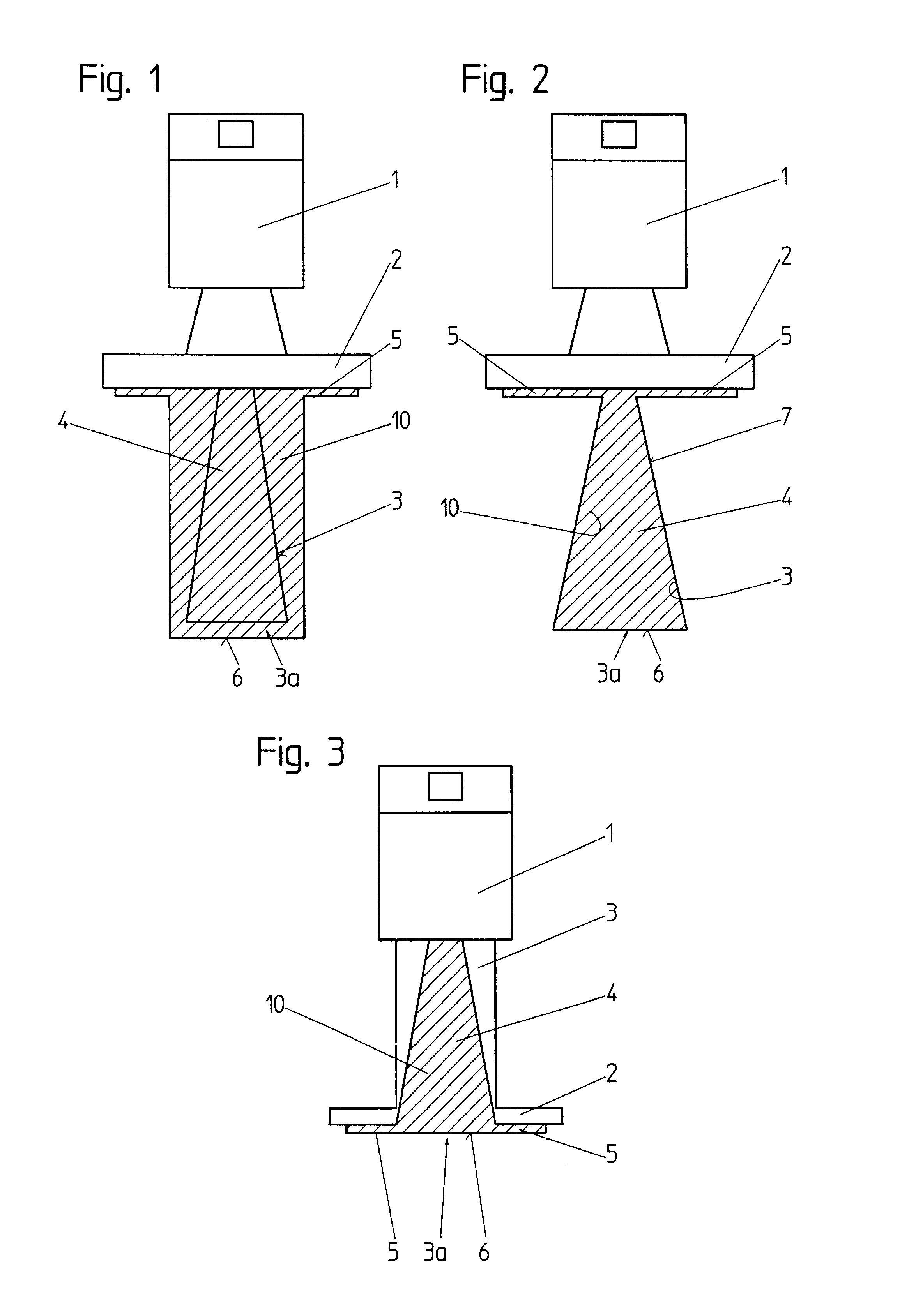
FIG. 1 a schematic side view of a radar-filling level measuring device with an inventive horn antenna,
second embodiment
FIG. 2 a schematic side view of a radar-filling level measuring device with an inventive horn antenna,
FIG. 3 a schematic side view of a radar-filling level measuring device with a further embodiment of an inventive horn antenna,
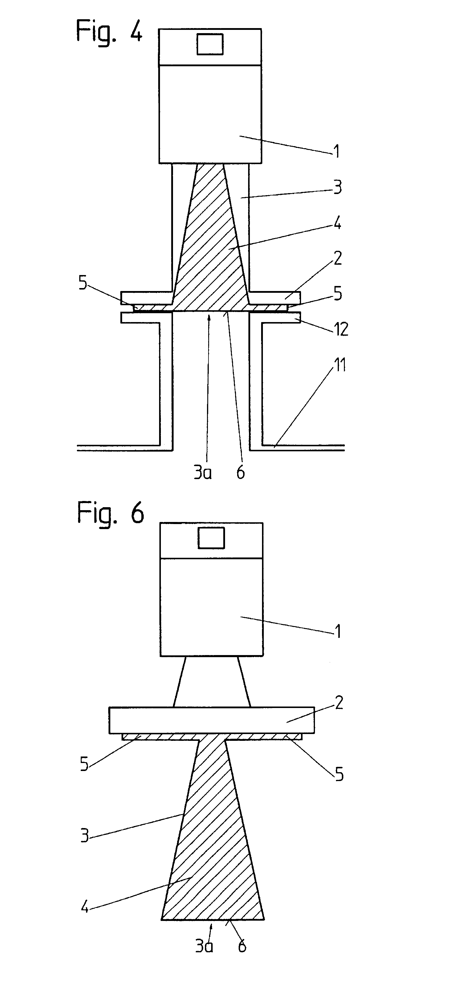
FIG. 4 a schematic side view of the filling level measuring device shown in FIG. 3, which is here placed on a flange of a vessel,
FIGS. 5a-5c in each case a schematic side view of a filling level measuring device as it is shown in FIGS. 3 and 4, the radiation opening of the horn antennas in the modification shown here being formed as a specifically configured radiation lens,
FIG. 6 a schematic side view of a further embodiment of a horn antenna according to the invention completely made of a dielectric material,
FIG. 7 a schematic sectional view of a level measuring device with an inventive horn antenna, and
FIG. 8 a schematic sectional view of a further level measuring device with a horn antenna according to a further embodiment of the invention.
PUM
 Abstract
Description
Claims
Application Information