Structure for interlocking connectors

a technology of interlocking connectors and connectors, which is applied in the direction of electrical apparatus, coupling device connections, printed circuits, etc., can solve the problems of unfavorable compactness of the overall size is not desirable, and it is difficult to render the couple of such connectors more compa

Inactive Publication Date: 2003-12-16
JST MFG CO LTD
View PDF6 Cites 28 Cited by
  • Summary
  • Abstract
  • Description
  • Claims
  • Application Information

AI Technical Summary

Benefits of technology

FIG. 5 is a perspective view of the socket connector in still another embodiment.

Problems solved by technology

It is however noted that those detents protruding sideways from the lateral sides of the base housing have inevitably caused an undesirably large overall size.
Thus, it has considerably been difficult to render more compacted the couple of such connectors.

Method used


Image

  • Structure for interlocking connectors
  • Structure for interlocking connectors
  • Structure for interlocking connectors

Examples


Embodiment Construction

Now some embodiments of the present invention will be described in detail, referring to the drawings.

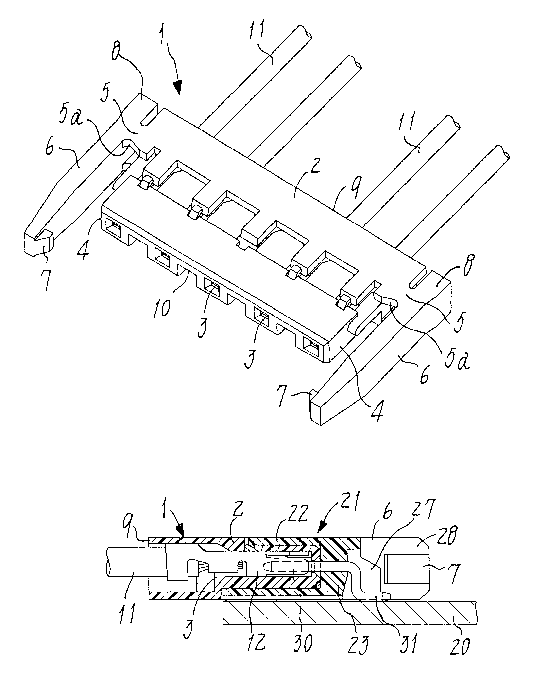
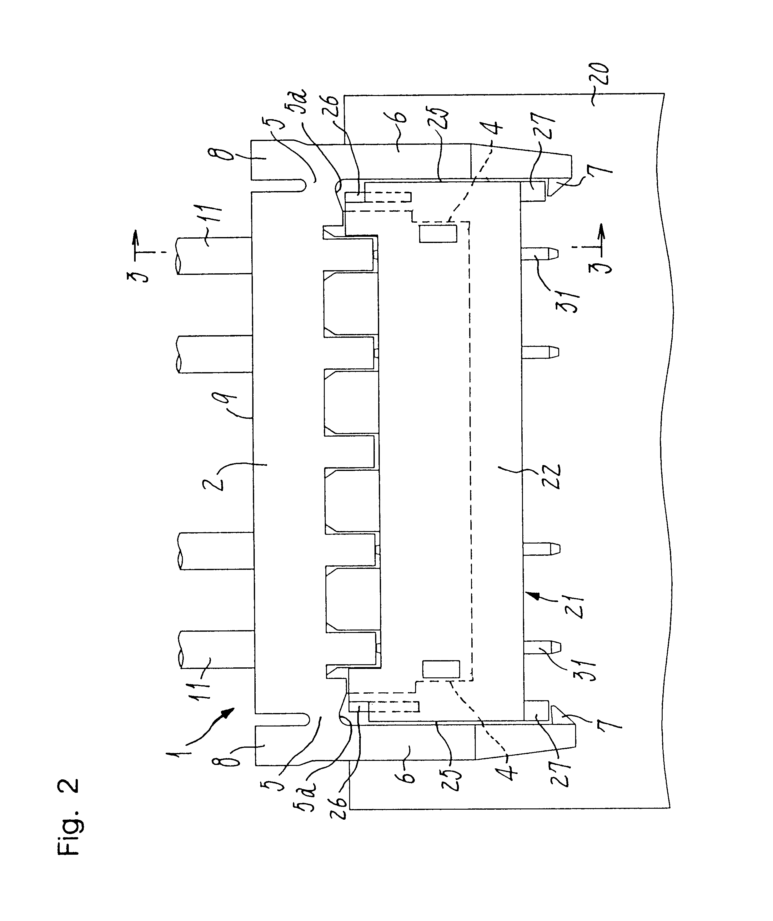
A socket connector involved in the present invention is shown as a perspective view thereof in FIG. 1 and generally indicated at the reference numeral 1. As seen in FIG. 2 that is a plan view, the socket connector 1 is to be fitted on a mating base connector 21 that has been surface mounted on a printed circuit board 20. These connectors are shown from another aspect in FIG. 3 that is a cross section taken along the line 3--3 in FIG. 2.

As seen in FIG. 1, the socket connector 1 comprises a socket housing 2 that is of a flat and rectangular shape elongated sideways. Compartments 3 are rectangularly cylindrical portions arranged side by side and at regular intervals in the socket housing 2 so as to accommodate therein socket contacts 12 separated from each other (see FIG. 3). Each contact 12 is secured to one of wire ends 11, with each compartment being a unit shaped to be a square cyli...


PUM


Abstract

A structure such that a socket connector manufactured less expensively can engage with a base connector more reliably, adapted to employment in high-voltage connectors of a reduced height. The socket connector (1) has a socket housing (2) in which socket contacts (12) secured on wire ends (11) are placed side by side. The base connector (21) is of a shape to be surface-mounted on a printed circuit board (20). The socket housing (2) has a pair of lock arms (6) extending forwards from a rear end of and along lateral sides (4) of the socket housing. The socket housing further has tie pieces (5) capable of elastic deformation and formed integral with the lateral sides so as to support and operatively connect the lock arms (6) to the socket housing. The lock arms (6) have fore ends formed integral with hooks (7) projecting inwards and towards each other, and the lock arms (6) further have push lugs (8) extending backwards from their rear ends so as to be located in rear of the tie pieces (5). When engaging the connectors one with the other, the lock arms (6) will be guided forwards along respective sides (25) of the base housing (22) until latched in place by and with the rear edge of this housing.

Description

The present invention relates to a structure for causing a base connector to interlock with a socket connector having wire ends secured thereto, wherein the base connector is surface mounted on a printed circuit board.PRIOR ARTExamples of such a locking structure have been known in the art as disclosed in the specifications and drawings of U.S. Pat. Nos. 4,008,941 and 4,376,565. In each of those prior art structures, a socket housing has lock arms respectively disposed on its lateral sides. Each lock arm has at its distal end a hook capable of engaging with the corresponding one of detents that protrude from lateral sides of a base housing. Those lock arms further comprise certain push portions that will be pressed to release the hooks off the detents so as to break the interlocking relationship between said connectors.It is however noted that those detents protruding sideways from the lateral sides of the base housing have inevitably caused an undesirably large overall size. Thus, ...

Claims


Application Information

Patent Timeline
Patent Type & Authority Patents(United States)
IPC IPC(8): H01R13/627H01R12/71H01R13/639
CPCH01R13/6273H01R13/639
Inventor ARAMOTO, KIYOSHIMIYAMOTO, DAICHI
Owner JST MFG CO LTD
Why Eureka
Try Eureka