High frequency telecommunication connector

a high-frequency telecommunication and connector technology, applied in the direction of coupling devices, two-part coupling devices, electrical equipment, etc., can solve the problems of circuit discontinuity, high manufacturing and assembly cost of cross-over conductors that follow irregular paths in connectors

Inactive Publication Date: 2003-12-16
COMMSCOPE INC
View PDF1 Cites 53 Cited by
  • Summary
  • Abstract
  • Description
  • Claims
  • Application Information

AI Technical Summary

Problems solved by technology

The use of spring terminal contact wires supported in a cantilevered fashion can contribute to circuit discontinuity caused by bent contacts, that are not aligned, or that make high impedance physical contact.
The use of cross-over conductors that follow irregular paths in a connector are expensive to manufacture and assemble.

Method used


Image

  • High frequency telecommunication connector
  • High frequency telecommunication connector
  • High frequency telecommunication connector

Examples


Embodiment Construction

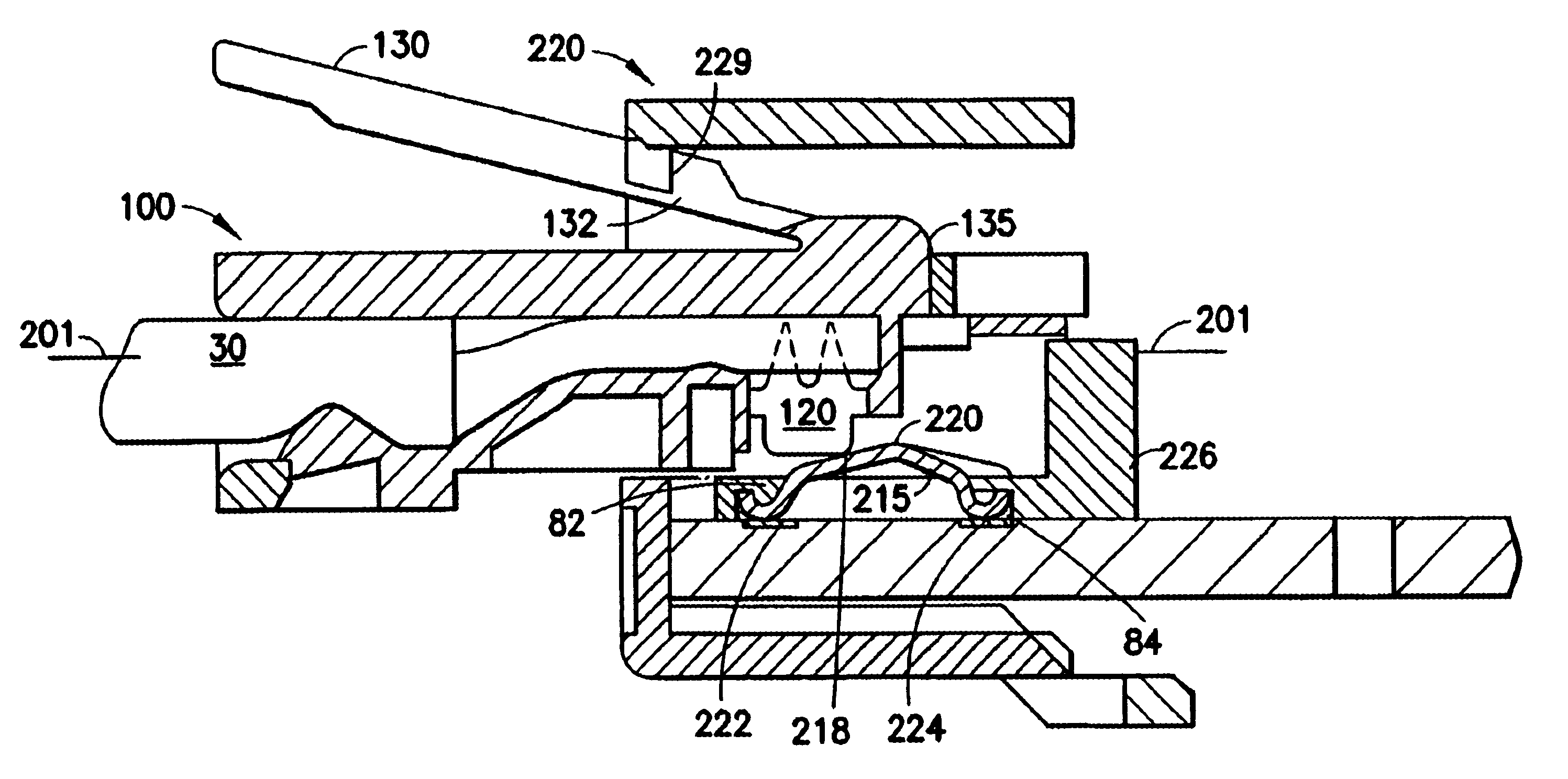
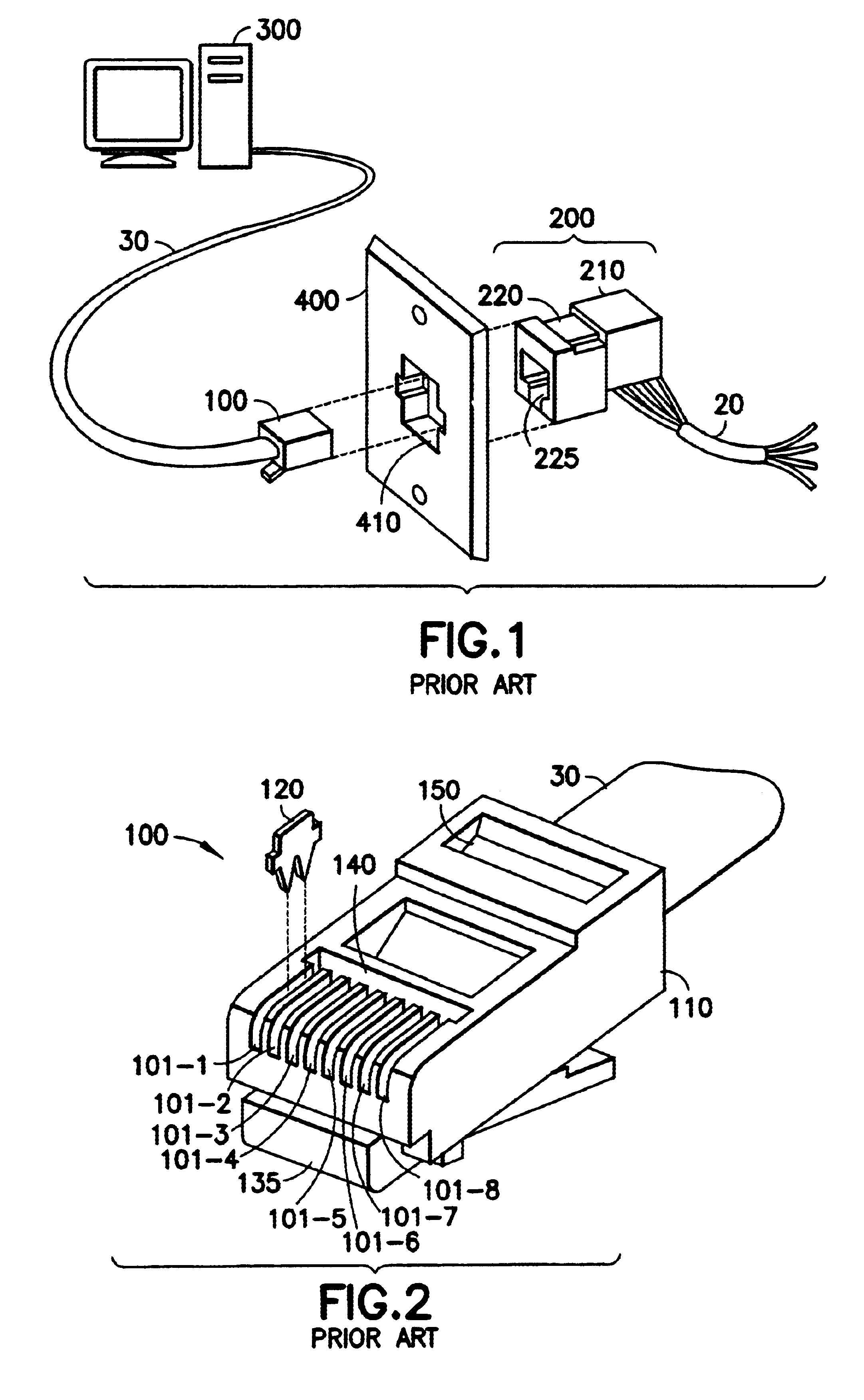
FIG. 1 depicts an assembly of interconnecting hardware which may be used in an electrical communication system. Thus, this hardware may for example be used to interconnect a high speed computer station 300 to an electrical cable 20 via standard telecommunications connecting apparatus such as a cord 30, a modular plug 100, and a modular jack 200. Illustrative specifications for such plugs and jacks can be found in subpart F of the FCC Part 68.500 Registration Rules. Modular jack 200 comprises a spring block assembly 210 and a jack housing 220 that interlock together to provide a convenient receptacle for receiving and releasably retaining the modular plug 100. Spring block assembly 210 includes a number of electrically conductive paths. The conductive paths terminate, at one end, in flexible arch shaped spring terminal contact wires having two legs connected together at an apex (hereinafter "jack springs") that may be formed, for example, from a conductive resilient material such as ...


PUM


Abstract

In accordance with the invention, there is provided a telecommunication jack that is free of cross-over sections, has cross-talk characteristics that approach Category 6 levels, and avoids the use of spring contact wires supported in a cantilevered fashion. This is achieved in a preferred implementation by spring terminal contact wires that are arch shaped. Each spring wire has a first leg having an end, a second leg having an end and an apex portion located between the first and second legs where the ends of the legs are supported on a wire board and each end makes electrical contact with separate conductive pads. When utilized in an operating circuit, one end and leg of a spring terminal contact wire is coupled to a conductive pad on the wire board that is in a current carrying signal path, and the other end and leg of that spring terminal contact wire is coupled to a different conductive pad on the wire board adapted for connection to a cross-talk compensating component. In accordance with the invention, both pads of the wire board are connected to a common spring terminal contact wire, although only one pad and one leg of the arch shaped spring wire may be in the current carrying signal path. The legs of the arch shaped spring terminal contact wires can be of equal or unequal length, the arch can be semi-circular, triangular or the like, and the conductive pads on the wire board of adjacent spring wire terminals can be either aligned or staggered in distance from the edge of the wire board.

Description

1. Field of the InventionThe present invention relates generally to wire and cable connectors and, more particularly, to electrical connectors for communication circuits that compensate for cross-talk along different signal paths within the connector.2. Description of the Related ArtConnectors for communication wires and cables are normally used to connect the ends of pairs of wires which define discrete signal paths. A typical industry type of communication connector is the RJ-45 communication connector. This connector contains eight wires to provide four pairs of terminal wires where each pair of wires defines a single signal path. Within the typical RJ-45 connector, the eight wires which make up the four pairs of conductors are closely spaced and normally follow paths which are parallel to each other for the length of the connector body. This close positioning of the wires strongly suggests that cross-talk may be induced between and among different pairs of wires within the RJ-45...

Claims


Application Information

Patent Timeline
Patent Type & Authority Patents(United States)
IPC IPC(8): H01R13/66H01R24/00
CPCH01R13/6658H01R13/6474Y10S439/941H01R13/6466H01R24/64
Inventor ARNETT, JAMIE R.GOODRICH, ROBERT R.REED, DAVID L.STRAUB, PAUL J.
Owner COMMSCOPE INC
Why Eureka
Try Eureka