Garden edging system

a technology for edging and gardens, applied in the field of garden edging systems, can solve the problems of increased cost, increased maintenance costs, and increased maintenance costs, and achieve the effects of reducing the length ratio, reducing maintenance costs, and being highly resistant to breakag

Inactive Publication Date: 2003-12-30
RICCOBENE MASONRY
View PDF31 Cites 65 Cited by
  • Summary
  • Abstract
  • Description
  • Claims
  • Application Information

AI Technical Summary

Benefits of technology

Another object of the invention is to provide edging units that are small, light weight and user friendly, and that, when installed, do not shift or tilt.
Each of the units is provided at its ends with a connecting face comprising a vertical rib and an adjoining vertical groove such that the ribs on the connecting faces of two adjoining units fit within the grooves in the connecting faces of the two units, thereby connecting the units and mitigating against relative movement, e.g., tilting or shifting. The connecting faces on all three types of edge units, straight, curved and corner, are the same so that the connections therebetween are universal and facilitate a myriad of border or edge designs.

Problems solved by technology

A long standing problem with prior edging units is that they are prone to breakage during manufacture and shipment, resulting in waste and economic loss.
Also, existing edgers are heavy and not user friendly.
Due to their sizes, the units frequently extend beyond the edges of conventional pallets and incur further damage during shipment and handling.
Shipment and handling of the curved units is particularly troublesome.
When multiple curved units are transported or handled (e.g., grasped by brick handling equipment such as a clamp cuber) the units will frequently break because of the spacing and lack of support at the mid-portions of the units.
Additionally, since the curved units cannot be fully nested, the number of units that can be loaded on a pallet is low.
Therefore, after installation, the units are free to slip, slide and tilt relative to one another destroying the aesthetics of the edging pattern or design.
A drawback of male-female connectors is that only one side of a unit (e.g., male end) can connect with a given end of an adjoining unit (e.g., female end).

Method used


Image

  • Garden edging system
  • Garden edging system
  • Garden edging system

Examples


Embodiment Construction

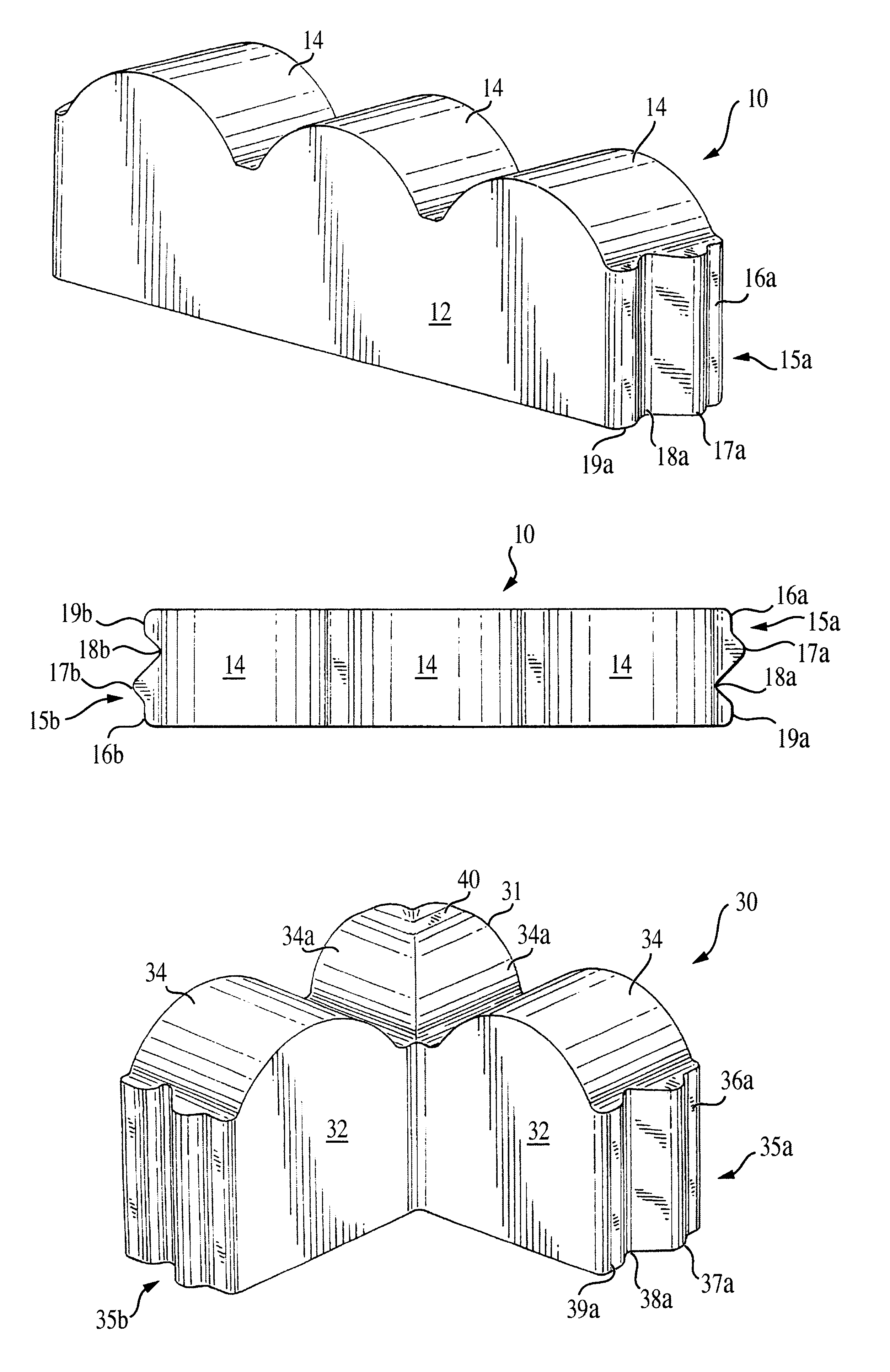
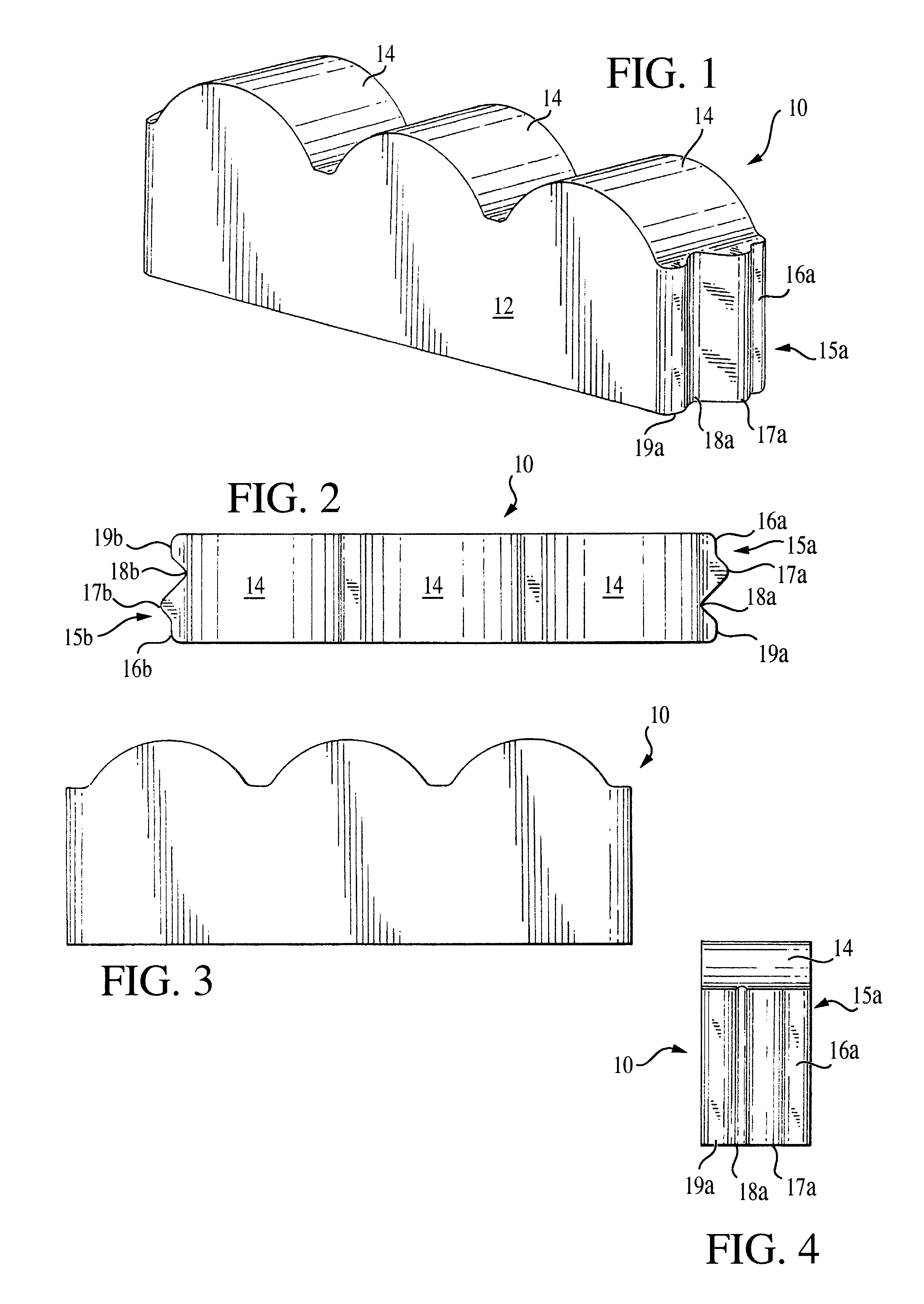
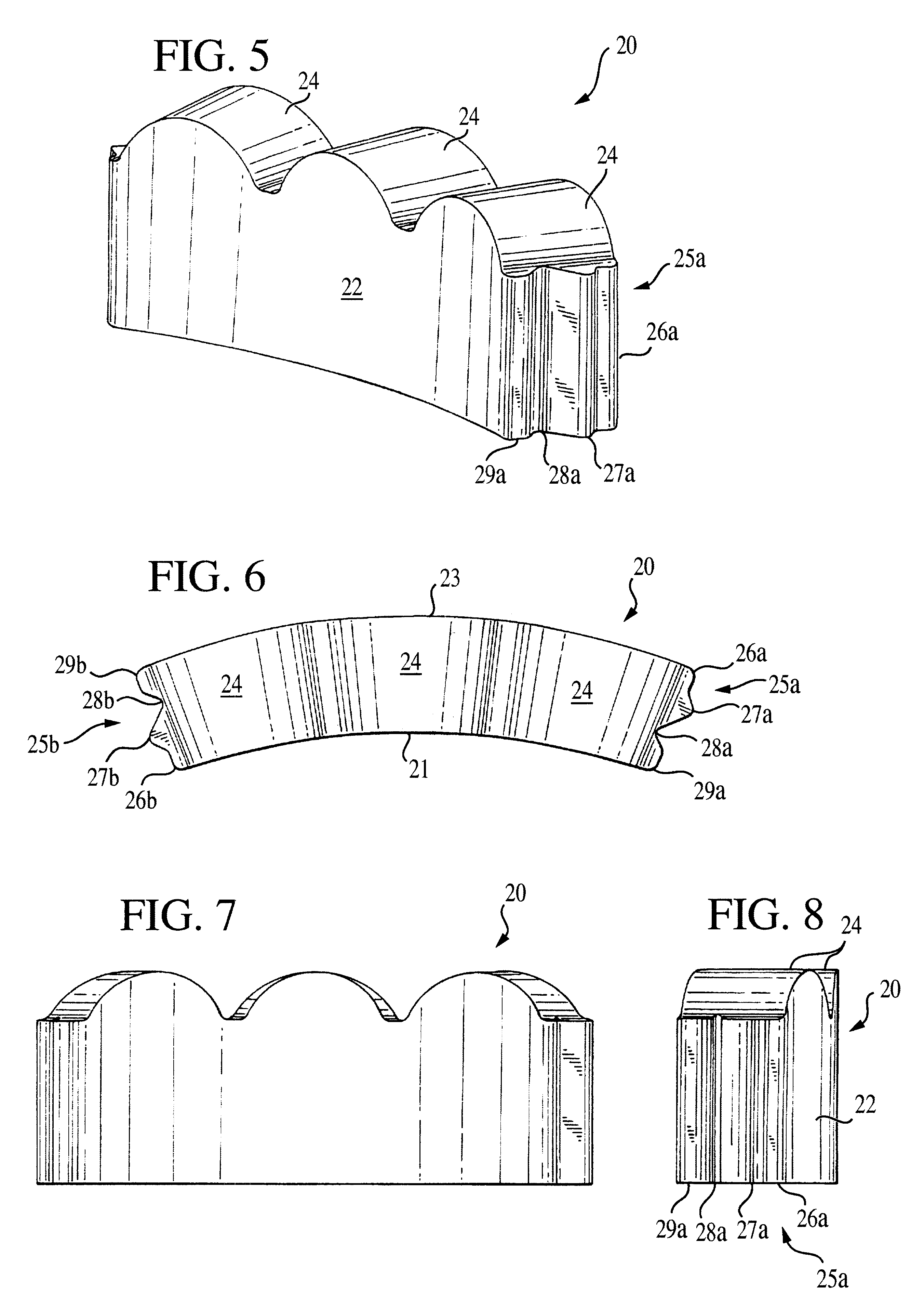
The following is a detailed description of preferred embodiments of the invention presently deemed by the inventor to be the best mode of carrying out his invention. The dimensions set forth herein for the three pieces or units of the edging system of the invention are the optimum dimensions for the units. Reasonable variations may be made within the skill of the art.

FIGS. 1, 2, 3 and 4 illustrate a preferred embodiment of the straight edging unit of the invention. The unit, indicated generally at 10, is preferably molded from a cementitious mixture, e.g., low or no slump concrete, and is comprised of a rectangular cubic body 12 and a scalloped top comprised of a plurality of scallops, preferably three scallops 14. The unit has a preferred length of 12 inches, a preferred thickness of two and one-quarter inches and a preferred overall height, including the scallops, of four and a quarter inches. Each scallop has a height of about one inch (31 / 32nds of an inch) and comprises an arc o...


PUM


Abstract

A garden edging system is made up of (a) one or more straight edger units, (b) one or more curved edger units and (c) one or more corner units. Each unit has a connecting face at each of its ends for connecting and holding adjacent units in end-to-end alignment with one another. The connecting faces facilitate the layout of a myriad of garden edging designs. The curved units have both their convex side and their concave side formed on the same arc of curvature so that a plurality of the units may be nested together with the concave side of each unit engaged flush against the convex side of the next adjacent unit. This facilitates packing and shipping of the units and mitigates against damage to the units. The units are dimensioned and sized to be stronger, more damage resistant, more versatile and more user-friendly than conventional edger bricks or tiles. A process of making the edger units is also disclosed.

Description

The invention relates to decorative edging for gardens and around trees, and particularly to an edging system comprised of concrete bricks or tiles of different shapes adapted to be arranged in end-to-end relationship in different configurations to define the edge or border of a garden.A popular form of garden edging is comprised of concrete or cement bricks or tiles adapted to be arranged in such a manner as to form a circle around a tree trunk or to define or accent the edge or border of a garden. A well known edger is the scallop edger, which is comprised of long, narrow and relatively tall bricks or tiles having an undulating or scalloped top. The bricks are adapted to be partially buried in the earth in end-to-end relationship to comprise a border. Conventionally, the bricks or tiles are of three types, namely, straight units, curved units and corner units, to facilitate the formation of various edge configurations or designs.The straight and curved units are typically 23 to 30...

Claims


Application Information

Patent Timeline
Patent Type & Authority Patents(United States)
IPC IPC(8): A01G1/08A01G9/28
CPCA01G1/08A01G9/28
Inventor RICCOBENE, THOMAS S.
Owner RICCOBENE MASONRY
Why Eureka
Try Eureka