Methods and system for characterizing the response of subsurface measurements to determine wellbore and formation characteristics

a technology of electromagnetic and subsurface measurement, applied in seismology for waterlogging, using reradiation, instruments, etc., can solve problems such as lack of reliable fullbore caliper measurement, process often employed to measure subsurface characteristics subject to significant errors, and inability to use wireline caliper measurements

Inactive Publication Date: 2003-12-30
SCHLUMBERGER TECH CORP
View PDF7 Cites 38 Cited by
  • Summary
  • Abstract
  • Description
  • Claims
  • Application Information

AI Technical Summary

Problems solved by technology

The processes often employed to measure the subsurface characteristics are subject to significant errors unless information on the borehole size, the borehole configuration, and the electric and geometric properties of the invaded zone are also taken into account.
There is a lack of a reliable fullbore caliper measurement while drilling.
Wireline caliper measurements may not be an option when critical decisions need to be made while drilling.
Furthermore, hole conditions will likely have changed by the time a wireline caliper is run.
Such mechanical apparatus have practical limitations and are limited in the range of diameter measurement they provide.
However, the techniques proposed with acoustic calipers entail measurements employing standoff and travel time calculations, resulting in data of limited accuracy.
Sound wave reflections in soft formations may also be too weak to be accurately detected, leading to loss of signals.
Downhole measurements are also af

Method used


Image

  • Methods and system for characterizing the response of subsurface measurements to determine wellbore and formation characteristics
  • Methods and system for characterizing the response of subsurface measurements to determine wellbore and formation characteristics
  • Methods and system for characterizing the response of subsurface measurements to determine wellbore and formation characteristics

Examples


Embodiment Construction

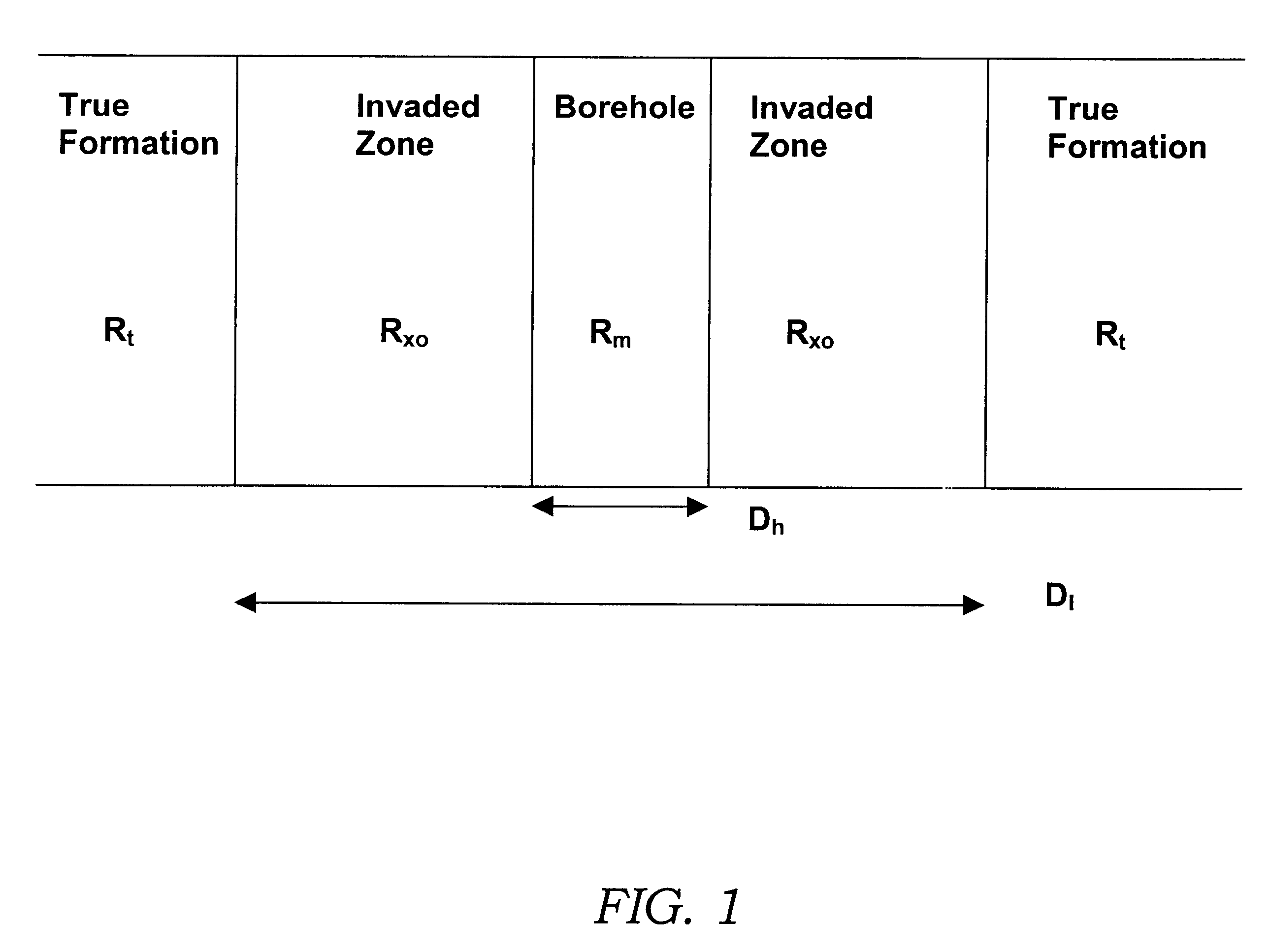
FIG. 1 illustrates the environment encountered during subsurface measurement with conventional well tools. For simplicity, an idealized step invasion profile is assumed. The relevant parameters of the formation model consist of two geometrical parameters, the borehole diameter D.sub.h, the invasion diameter D.sub.i, and three resistivity parameters, mud resistivity R.sub.m, invasion resistivity R.sub.xo, and formation resistivity R.sub.t. For focused measurements, it is clear that measurement current has to go through the borehole and invaded zone before entering the undisturbed formation. Thus, the resistivity measurement will be affected by the electrical properties of all these zones.

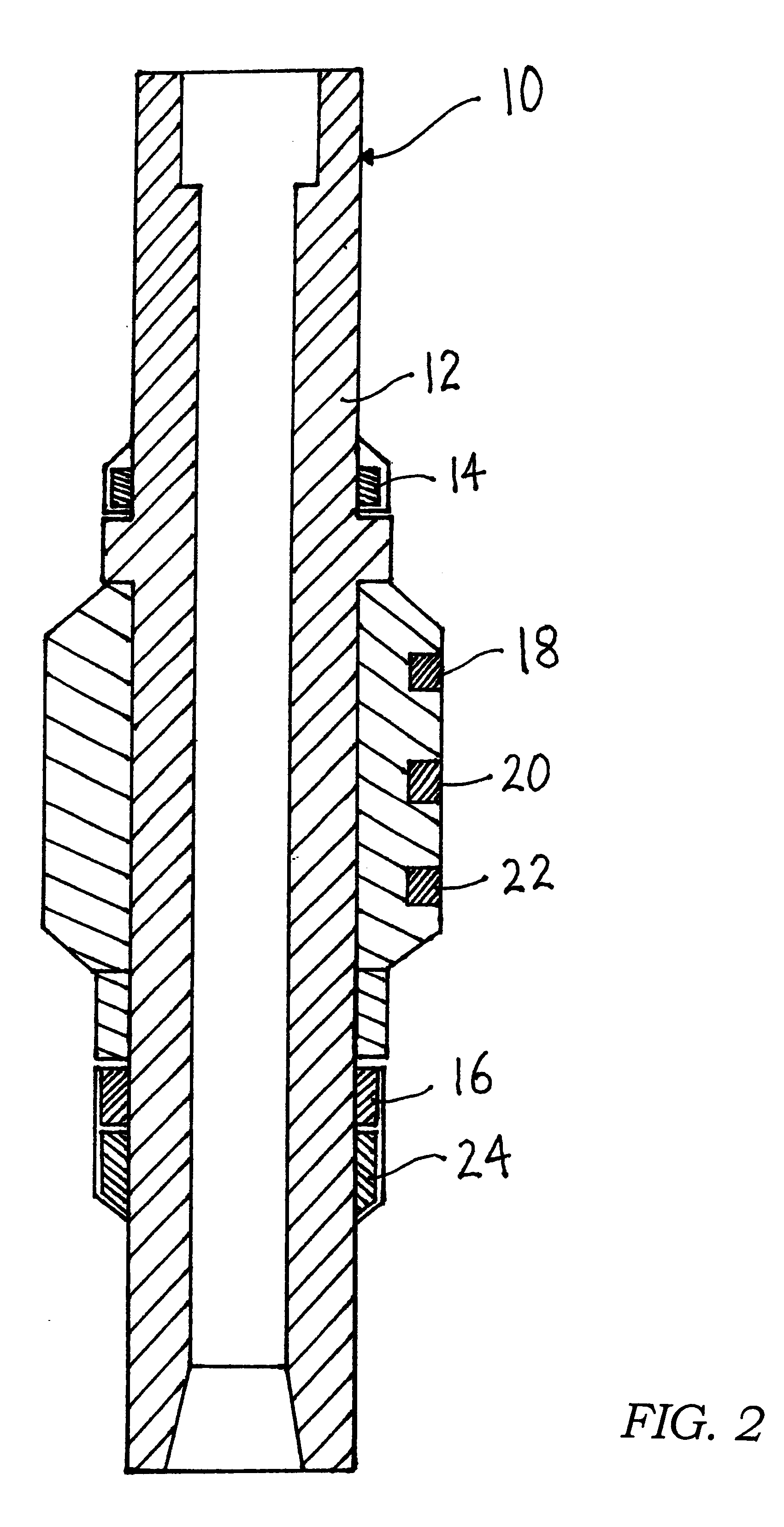
An embodiment of the invention utilizes multi-sensor azimuthal electric measurements to calculate caliper in different sectors of azimuthal directions and, at the same time, determine the properties of the true rock formation surrounding the borehole. An LWD instrument particularly suited for use wit...


PUM


Abstract

Methods and systems are disclosed for characterizing the response of a subsurface resistivity measurement to determine a characteristic of a borehole within the subsurface and/or a characteristic of a formation surrounding the borehole. Generally the methods include obtaining subsurface resistivity measurement data with a well tool disposed within the borehole and fitting the obtained resistivity measurement data to an equivalent electric circuit model to determine the borehole and/or formation characteristic. The circuit model of these embodiments is representative of a response of the well tool to borehole and formation parameters. The systems generally include a well tool and an apparatus adapted to be coupled to the well tool. The apparatus includes means for receiving measurement data generated by the well tool, means for storing model parameters representative of a response of the well tool to borehole and formation properties, and means for comparing the received measurement data to the stored model parameters to determine the borehole and/or formation characteristic. The disclosed equivalent circuit model is characterized by an electric circuit having at least one resistor-in-parallel component.

Description

1. BACKGROUND OF THE INVENTION1.1 Field of the InventionThis invention relates generally to a method and system for characterizing subsurface electromagnetic (EM) measurements to determine wellbore and formation properties and, more particularly, to a technique for obtaining the caliper of a wellbore and the electric and geometric properties of the surrounding rock formations from subsurface EM measurements. The invention has general application in the well logging art, but is particularly useful in measuring-while-drilling.1.2 Description of Related ArtIn order to improve oil and gas drilling operations, it is necessary to gather as much information as possible on the properties of the subsurface earth formation where deposits are believed to exist. Such properties include the resistivity of the earth formations traversed by the well borehole, in addition to data on the properties and configuration of the borehole itself.The collection of downhole information, also referred to as l...

Claims


Application Information

Patent Timeline
IPC IPC(8): G01V3/18G01V3/20
CPCG01V3/20
Inventor LI, QIMING
Owner SCHLUMBERGER TECH CORP
Why Eureka
Try Eureka