
Planet gear

a technology for planes and wheels, applied in the field of plane gears, can solve the problems of not being able to adapt the strength of springs to the torque, and one half of the tooth flanks of the sun wheel carrying work

Inactive Publication Date: 2004-01-13
MAXON MOTOR AG
View PDF7 Cites 11 Cited by
  • Summary
  • Abstract
  • Description
  • Claims
  • Application Information

AI Technical Summary

Benefits of technology

For this purpose, the invention provides that the ring gear is formed in two pieces on a plane perpendicular to the axis of rotation of the planet carrier, wherein the two halves of the ring gear can be rotated against each other and thereby effect a radial shift of the planet wheel in the direction towards the sun wheel in order to reduce backlash.
Planet gears with divided ring gears are known per se. For this purpose, reference is for instance made to DE 37 38 607 A1. The multi-step planet gear that is known there also has divided planet wheel besides having a divided ring gear. By rotating the halves of the ring gear against each other by means of adjusting screws, the two planet wheels are positioned against each other so that a possible backlash between the ring gear and the planet wheels is avoided. However, the disadvantage thereof is that in one direction of rotation only one half of the tooth flanks of the sun wheel perform the carrying work. If it is intended to transfer the same power by this gear as transferred by a conventional planet gear, the axial overall length of the gear is compulsorily increased. In contrast thereto, the gear according to the present invention provides that only the ring gear is divided but not the planet wheels. Instead, the planet wheels are supported in a radially movable manner so that when rotating the ring gear halves, not only the backlash between the planet wheel and the ring wheel is reduced, but the backlash between the sun wheel and the planet wheel is also reduced due to the radial shift in the direction towards the sun wheel. It is advantageous that the tooth flanks of the sun wheel carry across the sun wheel's entire axial length so that despite the reduction of backlash, the overall dimensions of the planet gear do not have to be changed.
An especially preferred embodiment provides a combination of a spring-elastic pre-positioning of the two halves of the ring gears and their subsequent relative fixing. For this embodiment, the springs positioning the two halves of the ring gear against each other are merely required for a freedom from backlash being produced e.g. during idle running or in the case of a very small load. Then, the two halves of the ring gear are fixedly positioned against each other, e.g. by means of a screw, so that the springs do not have to transfer a torque.
Such a coupling of the halves of the ring gear via a train of gear is particularly advantageous if the trains of gear of the halves of the ring gear of several gear steps are connected to one another. Then, all gear steps of the planet gear can be adjusted in a manner free from backlash by one single operation of the train of gears.
A solution especially easy to realize provides that the halves of the rings gear are connected to one another via at least one fastening screw arranged on a parallel axis of rotation which penetrates the halves of the ring gear, wherein in at least one half of the ring gear the bore for the screw has backlash in the tangential direction of the ring gear in a manner that the half of the ring gear may move tangentially with respect to the screw. That means that the screw can be fixed tangentially in one half of the ring gear, wherein the other half of the ring gear has a bore with a tangential backlash so that the two halves of the ring gear can be slightly rotated against each other. Since the backlash to be eliminated in the gear is usually not very grerat, a relatively small difference in dimension between the bore and the outer diameter of the fastening screw is sufficient.
In particular when higher torques are to be transferred by the gear, it is also of advantage if at least two diametrally opposing fastening screws are arranged.

Problems solved by technology

However, the disadvantage thereof is that in one direction of rotation only one half of the tooth flanks of the sun wheel perform the carrying work.
The strength of the springs must therefore not be adapted to the torque to be transferred by the gear.

Method used


Image

  • Planet gear
  • Planet gear
  • Planet gear

Examples


Embodiment Construction

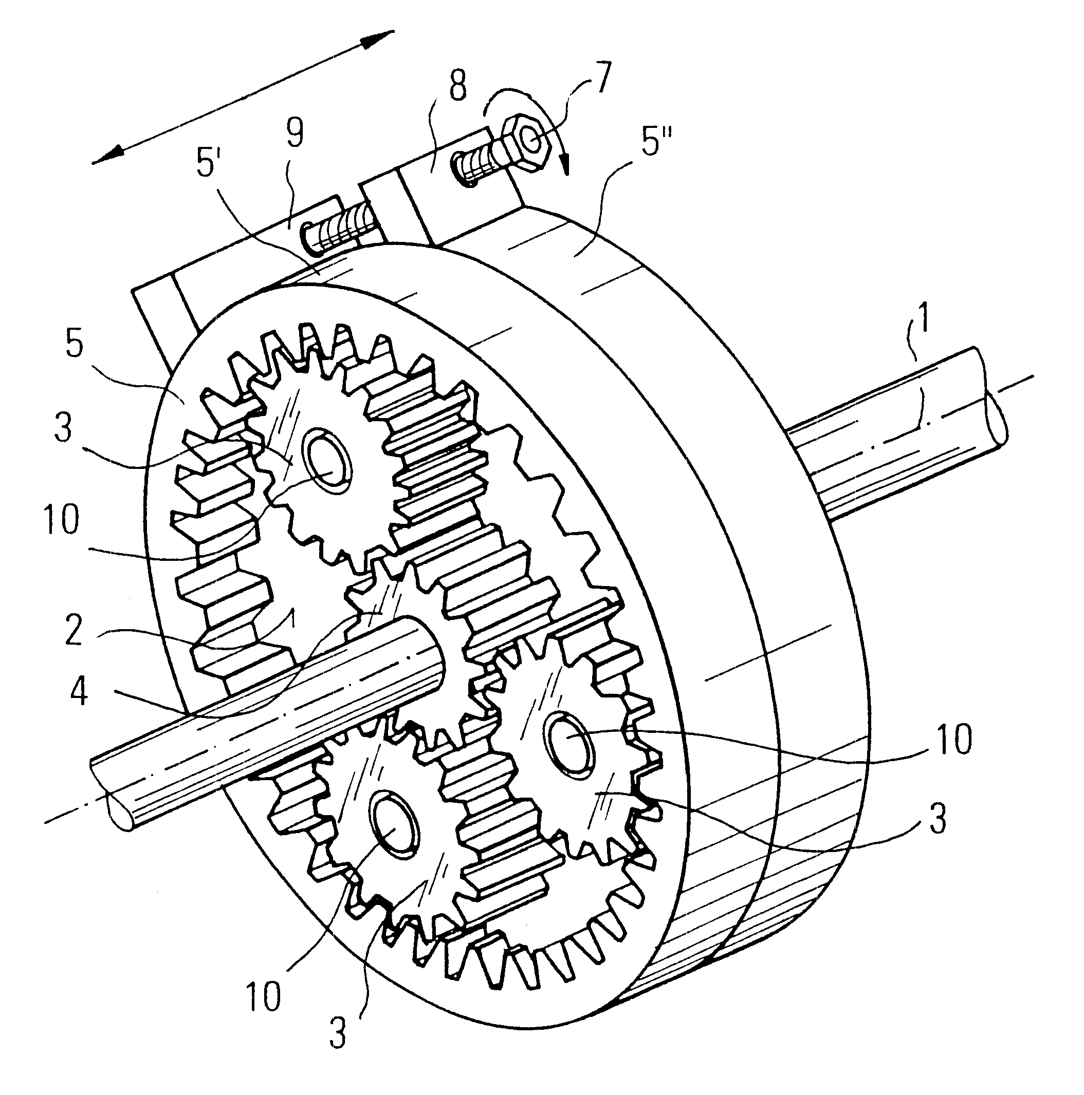
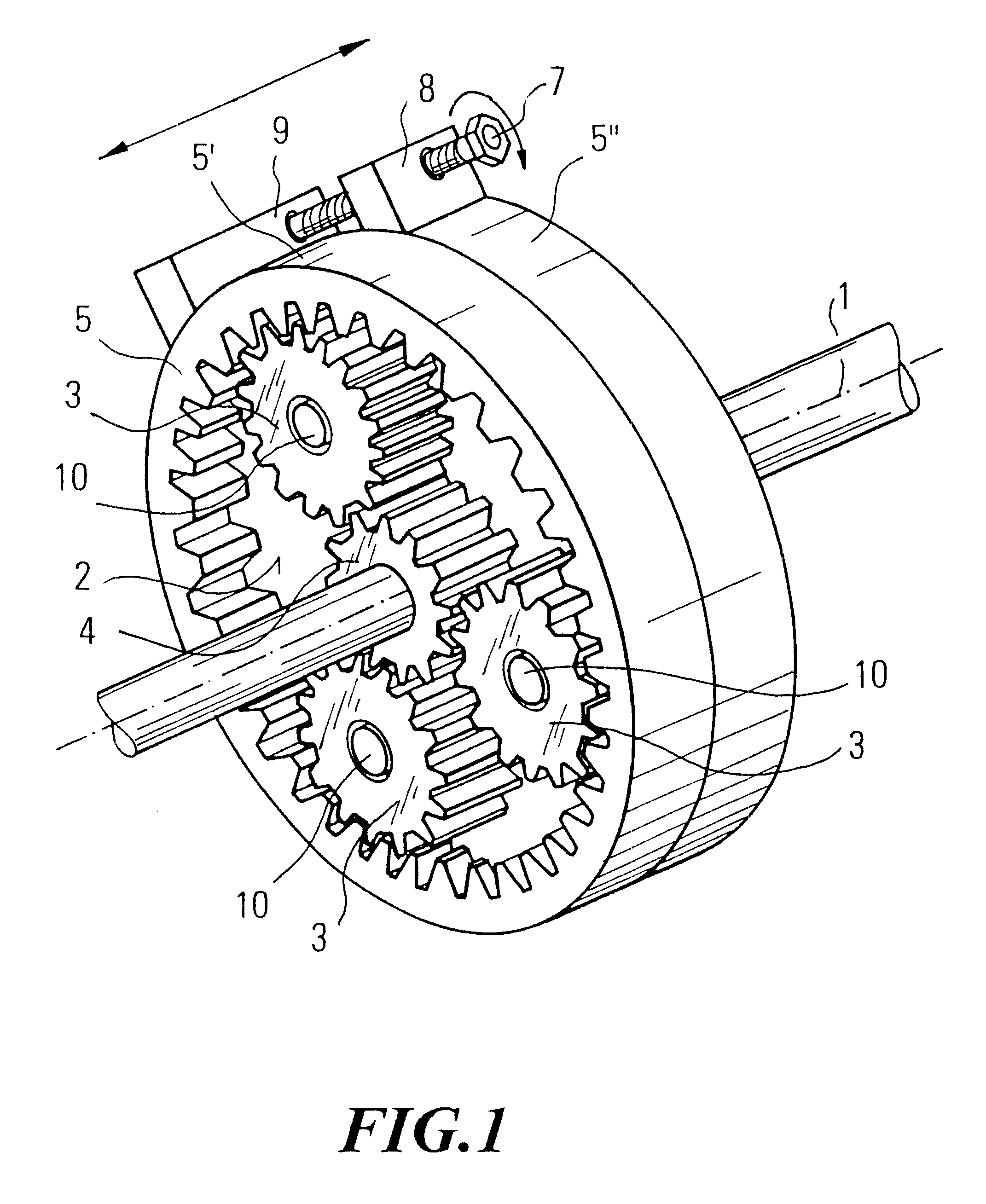
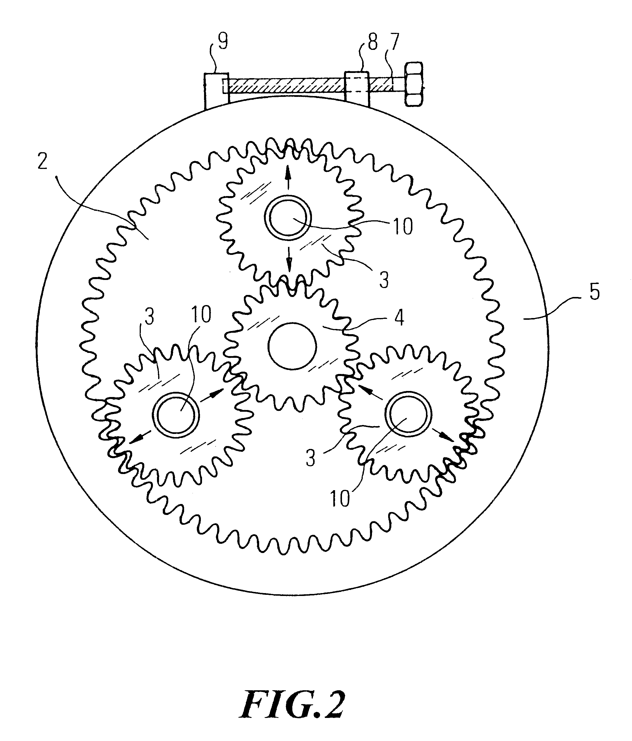
In the drawings, a planet gear with a planet carrier 2 rotating around a gear axle 1, planet wheels 3 and a sun wheel 4 is shown. The planet carrier 2 is encompassed by a ring gear 5 whose teeth mesh with the teeth of the planet wheels 3. The ring gear 5 is divided into two halves 5' and 5". The one half 5' is fixedly connected to the housing 6, whereas the other half 5" can be rotated against the first half. As may be seen from FIGS. 1 and 2, the rotatability is effected there by means of an adjusting screw 7, the thread thereof engaging on the one hand a pedestal 8 of the movable half 5" of the ring gear and the other end thereof being supported at a support block 9, which is connected to the fixed half 5' of the ring gear.

The planet wheels 3 are arranged on axle journals 10 of the planet carrier 2, at such a radial backlash that the planet wheels 3 are movable radially between the sun wheel 4 and the ring gear 5. This movability can in particular well be seen from FIG. 2. In orde...


PUM


Abstract

The invention relates to a planet gear having a planet carrier rotatable around an axis of rotation, comprising at least one planet wheel arranged on the planet carrier, a sun wheel and a ring gear, wherein the planet wheel is arranged in a movable manner at least radially with respect to the axis of rotation of the planet carrier. To minimize the backlash of a planet gear of this type, it is further provided that the ring gear is formed in two pieces on a plane perpendicular to the axis of rotation of the planet carrier, wherein the two halves of the ring gears can be rotated against each other and thereby effect a radial shift of the planet wheel in the direction towards the sun wheel in order to reduce backlash.

Description

This application is a continuation of Application No. 101 10 282.8 filed in Germany on Mar. 2, 2001, to which this application claims priority under 35 U.S.C. .sctn.119 and / or 365.RELATED ARTThe present invention relates to a planet gear comprising a planet carrier rotatable around an axis of rotation, at least one planet wheel arranged on the planet carrier, a sun wheel and a ring gear, wherein the planet wheel is arranged movably at least radially with respect to the axis of rotation of the planet carrier.A planet gear of this type is known from DE 195 46 586 and from EP 0 779 449. The radial movability of the planet wheels with respect to the planet carrier effects in the known planet gear a significant increase of the life, which is obviously a result of the fact that static over definitions are avoided. However, it proved that the demands on the planet gear are not only the demand for a longer life but also that freedom from backlash is increasingly required in particular for c...

Claims


Application Information

Patent Timeline
IPC IPC(8): F16H57/12F16H1/28F16H57/00
CPCF16H1/2863F16H57/12Y10T74/19623F16H1/46
Inventor FUTTERER, BODO
Owner MAXON MOTOR AG
Learn More