Multi-purpose float equipment and method

a float and multi-purpose technology, applied in the direction of drilling casings, drilling pipes, borehole/well accessories, etc., can solve the problems of surge pressure, surge pressure may be particularly high, and pressure may damage the formation

Inactive Publication Date: 2004-01-20
FORUM US
View PDF16 Cites 87 Cited by
  • Summary
  • Abstract
  • Description
  • Claims
  • Application Information

AI Technical Summary

Problems solved by technology

However due to the volume displaced by the tubular string, surge pressure is created during the process of lowering the casing into the fluid filled wellbore.
The surge pressure may damage the formation as fluid is highly compressed and forced into the formation.
The surge pressure may be especially great when running close tolerance casings or liners.
While devices have been used to permit fluid flow into the casing as it is lowered to thereby reduce surge pressure, problems may still occur due to limited internal casing diameters that restrict the volume of fluid flow and / or restrictions in the casing internal diameter due, for instance, to the internal diameter of float valves in the float equipment.
Moreover, cuttings from the well bore may collect and bridge, for instance adjacent restrictions in the casing string, to create additional problems.
Moreover, damage may occur to internal elements such as hydraulically activated liner hanger equipment, float valves, sealing elements such as seats for the float valves, or other elements, due to the abrasive fluids or cuttings from the wellbore that flow into the casing string.
Although either of the jets are useful, float shoes having both types of fluid ports or jets are less effective because the operation of one naturally interferes with the operation of the other.
However, the use of both downwardly and upwardly facing jets dilutes the function of each type of jet.

Method used


Image

  • Multi-purpose float equipment and method
  • Multi-purpose float equipment and method
  • Multi-purpose float equipment and method

Examples


Embodiment Construction

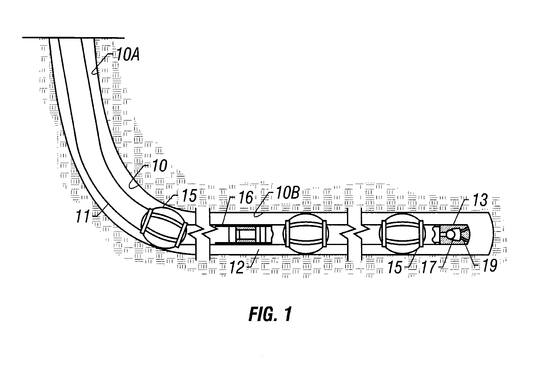
Referring now to the drawings and, more specifically to FIG. 1, there is disclosed casing string 11 within borehole 10 in accord with the present invention. The drilled borehole or wellbore 10 may be substantially vertical and / or have horizontal components. For instance, wellbore 10 may have relatively vertical sections such as section 10A and / or may have relatively horizontal sections such as section 10B. As the tubular string, such as a casing / liner string 11, is lowered into wellbore 10, it may be desirable to centralize tubular string 11 within borehole 10 by use of centralizers such as centralizers 15. Annulus 12 is defined between tubular string 11 and borehole 10. The present invention may be used with tubular strings including either casing strings or liners.

The present invention provides the ability for casing / liner 11 to self-fill as it is being run into wellbore 10. This self-filling action can significantly reduce surge pressure on the formation, and also reduce running ...


PUM


Abstract

A float shoe / collar apparatus and method for multi-purpose use in running a tubular string such as a casing string or liner into a wellbore and for optimizing cementing operations. In one presently preferred embodiment, the apparatus permits auto filling of the tubular string as the string is lowered into the wellbore. Circulation can be effected through down jets for washing the wellbore as necessary. After the tubular string is positioned, the down jets can be blocked off and up jets opened to thereby direct cement upwardly to optimize cement placement. Check valves can also be activated to prevent flow from the wellbore into the tubular string. In one embodiment, the apparatus comprises an inner member and tubular member. The inner member is movable upon release of shear pins to cause longitudinal movement relative to the outer member. The movement of the inner member may close a plurality of downward jets and may also open a plurality of upward jets, if desired. The apparatus may also be equipped with a set of check valves which can be held open on run in, and subsequently activated to thereby automatically close upon cementing to prevent "u-tubing" of fluid back into the casing. In another embodiment a float collar comprises the same valve / valves as the float shoe, without jets. This float collar may be run in conjunction with a guide shoe, with or without jets.

Description

This invention relates generally to apparatus and methods for use in well completions and, more particularly, is operable for multiple purposes during the insertion and cementing of tubular strings such as casing and liners in the well bore.BRIEF DESCRIPTION OF THE PRIOR ARTFor instance, in vertical or horizontal boreholes, or sections of a well having vertical and horizontal boreholes, one or more casing strings may be lowered into the hole and anchored therein by pumping a column of cement into the annulus between the casing string and the wall of the borehole. When lowering casing / liner into the wellbore, it has become conventional practice to fill the casing / liner string with drilling fluid. However due to the volume displaced by the tubular string, surge pressure is created during the process of lowering the casing into the fluid filled wellbore. The surge pressure may damage the formation as fluid is highly compressed and forced into the formation. The surge pressure may be es...

Claims


Application Information

Patent Timeline
Patent Type & Authority Patents(United States)
IPC IPC(8): E21B17/00E21B34/00E21B17/14E21B34/14
CPCE21B17/14E21B21/10E21B34/14E21B34/142
Inventor MUSSELWHITE, JEFFREY D.EHLINGER, JEFFRY C.ALLAMON, JERRY P.MILLER, JACK E.
Owner FORUM US
Why Eureka
Try Eureka