Pumpdown valve plug assembly for liner cementing system

a technology of cementing system and valve plug, which is applied in the direction of balloon catheter, borehole/well accessories, surgery, etc., can solve the problems of pressure buildup under the liner, loss of expensive drilling fluid, and two problems with respect to conventional cementing apparatus

Inactive Publication Date: 2001-11-06
BLACKHAWK SPECIALTY TOOLS
View PDF7 Cites 80 Cited by
  • Summary
  • Abstract
  • Description
  • Claims
  • Application Information

AI Technical Summary

Problems solved by technology

Two problems exist with respect to conventional cementing apparatus.
First, the flow resistance of two above-identified flow paths may be high and thus cause a pressure buildup below the liner.
This pressure buildup can: (a) cause damage to the formation; (b) result in loss of expensive drilling fluid; and (c) result in the liner sticking against the side of the borehole, which means that the liner does not go to the bottom of the hole.
Second, the small opening through the float valve may, and often does, become plugged with cuttings and contaminants due to its small size and the highly contaminated environment in which it is used.
Nonetheless, any plugging of the float valve at the lower end of the liner can, and very well may, render the surge pressure reduction system of the '881 patent ineffective.

Method used


Image

  • Pumpdown valve plug assembly for liner cementing system
  • Pumpdown valve plug assembly for liner cementing system
  • Pumpdown valve plug assembly for liner cementing system

Examples


Embodiment Construction

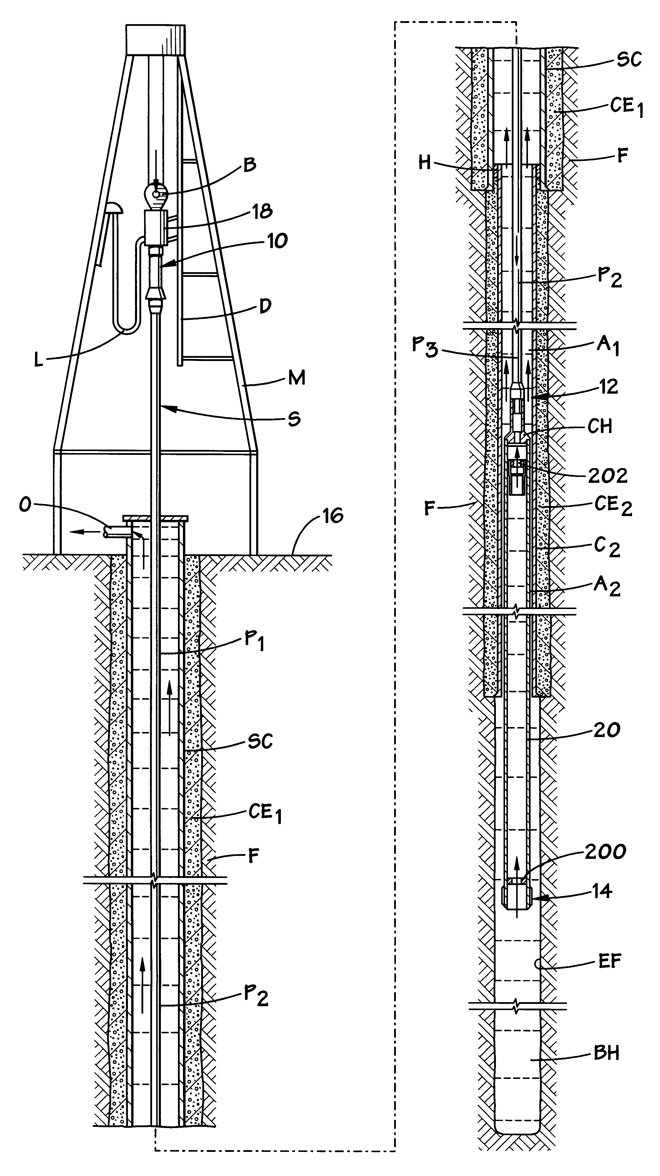
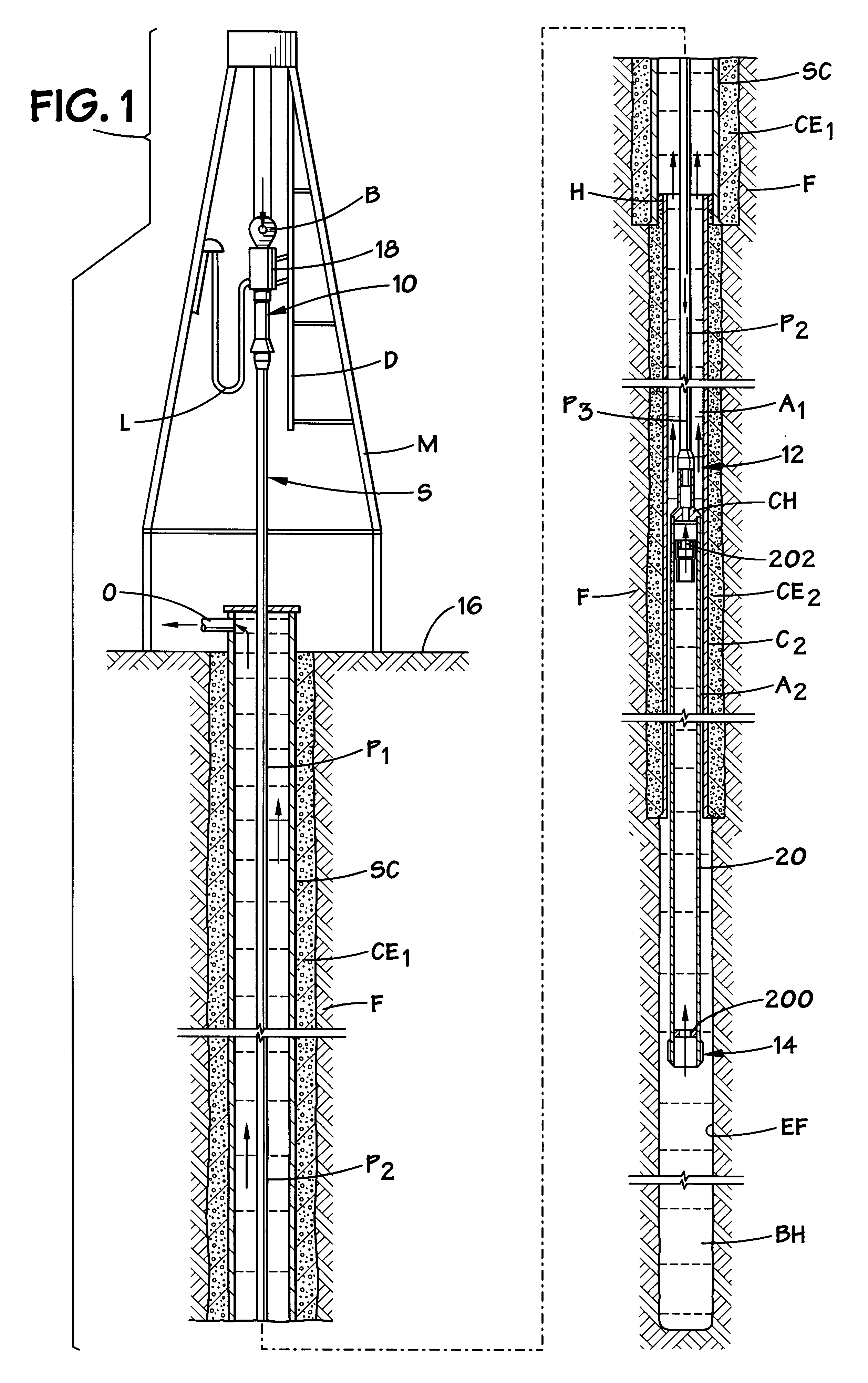
In oilfield operations, a "casing liner" and a "subsea casing string" are tubular members which are run on drill pipe. The term "casing liner" is usually used with respect to drilling operations on land, while the term "subsea casing string" is used with respect to offshore drilling operations. For ease of reference in this specification, the present invention is described with respect to a "casing liner." In the appended claims, the term "tubular member" is intended to cover either a "casing liner" or a "subsea casing string."

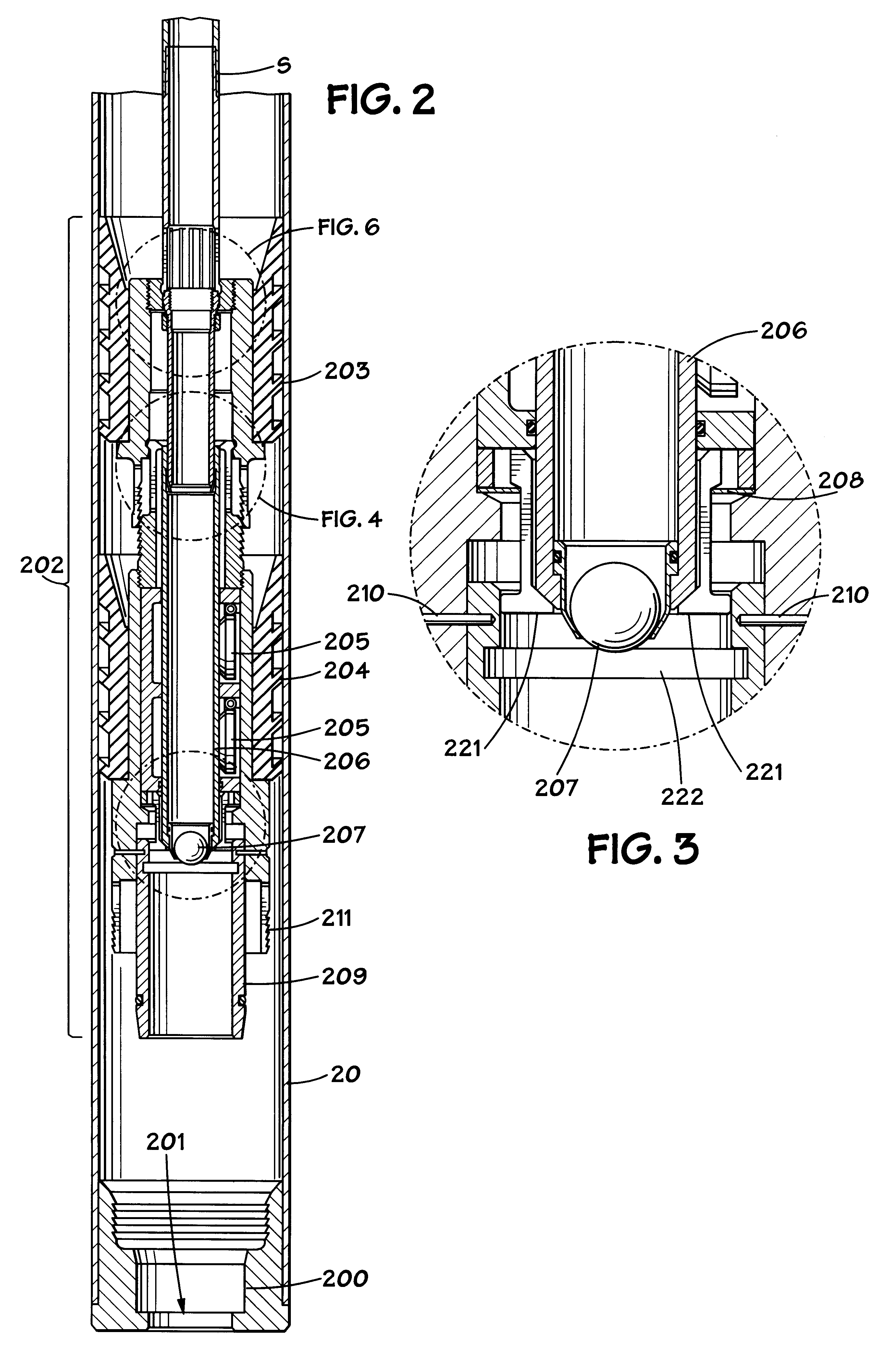
With reference to FIG. 1, the mast M suspends a traveling block B, which supports a top drive 18, such as manufactured by Varco B.J. Drilling Systems, that moves vertically on the TDS-65 block dolly D, as is known by those skilled in the art. An influent drilling fluid line L connects the drilling fluid reservoir (not shown) to the top drive 18. Though a kelly, a kelly bushing and a rotary table are not shown, the launching manifold 10 is designed to alternati...


PUM


Abstract

Method and apparatus are disclosed for use in cementing a tubular member which is run into a borehole using a drill string. A landing collar is attached to the tubular member near the bottom of the tubular member, and the landing collar has an opening at least five inches in diameter. A liner wiper assembly is releasably suspended from the drill string. The liner wiper assembly comprises a lower liner wiper plug comprising float valves and an upper liner wiper plug. With the method and apparatus of the present invention, plugging problems are minimized.

Description

1. Field of the InventionThe present invention relates to apparatus for use in cementing any tubular member that is run or landed with a string of drill pipe.2. Description of the Prior ArtPrior art liner cementing equipment includes a flapper or a float valve at the bottom of the liner. The flapper is conventionally held open by a breakable plastic tab which is actuated (i.e., broken) by a drop ball when the cementing operation is to begin. Since the drop ball which is used to activate the float valve must be small enough to pass through the drill string, the maximum float valve opening size for a 133 / 8" liner may be on the order of 2 to 3" in diameter. As the liner is lowered into the well bore, the fluid in front of the liner must be displaced to flow through the bottom opening in the float valve as well as around the outside annulus defined by the well bore and the liner.Two problems exist with respect to conventional cementing apparatus. First, the flow resistance of two above-...

Claims


Application Information

Patent Timeline
Patent Type & Authority Patents(United States)
IPC IPC(8): A61M25/10A61M29/02E21B33/13E21B33/16A61F2/958
CPCA61M25/10A61M25/1002A61M29/02E21B33/16A61M2025/105A61M2025/1086E21B33/165
Inventor ALLAMON, JERRY P.MILLER, JACK E.
Owner BLACKHAWK SPECIALTY TOOLS
Why Eureka
Try Eureka