Implantable prosthetic valve

a prosthetic valve and implantable technology, applied in the field of implantable devices, can solve the problems of increased hydrostatic pressure, pain, swelling and edema, changes in skin color,

Inactive Publication Date: 2006-02-02
MEDTRONIC 3F THERAPEUTICS
View PDF17 Cites 932 Cited by
  • Summary
  • Abstract
  • Description
  • Claims
  • Application Information

AI Technical Summary

Benefits of technology

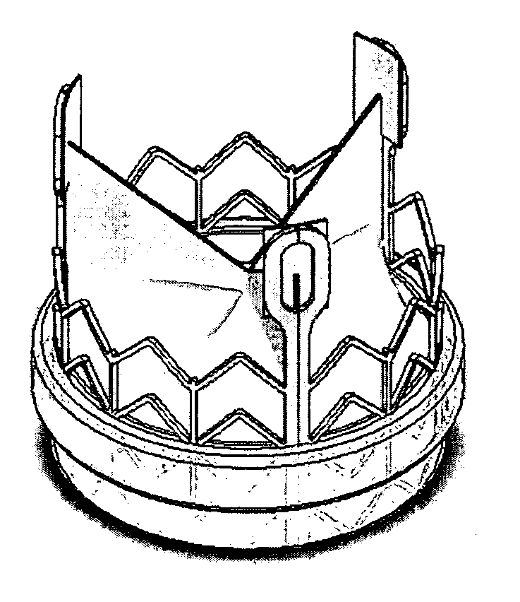
[0103] In yet another embodiment of the present invention, a valve assembly is provided in which the vertical components of the anchoring structure are limited to the commissural posts between sinus cavities, thereby minimizing contact between mechanical components and fluid, as well as providing flow to vessels located in the valve sinus.
[0104] In still another embodiment of the present invention, a valve is provided that firmly attaches to the valve sinus, obviating the need for suturing to secure the valve placement.

Problems solved by technology

When valves exhibit abnormal anatomy and function as a result of valve disease or injury, the unidirectional flow of the physiological fluid they are designed to regulate is disrupted, resulting in increased hydrostatic pressure.
For example, venous valvular dysfunction leads to blood flowing back and pooling in the lower legs, resulting in pain, swelling and edema, changes in skin color, and skin ulcerations that can be extremely difficult to treat.
Lymphatic valve insufficiency can result in lymphedema with tissue fibrosis and gross distention of the affected body part.
Regardless of their etiology, all valvular diseases result in either stenosis, in which the valve does not open properly, impeding fluid flow across it and causing a rise in fluid pressure, or insufficiency / regurgitation, in which the valve does not close properly and the fluid leaks back across the valve, creating backflow.
Such open heart surgery is particularly invasive and involves a lengthy and difficult recovery period.
Such contact is capable of contributing undesired stress on the valve leaflet.
As mentioned above, an open-heart valve replacement is a long tedious procedure.

Method used


Image

  • Implantable prosthetic valve
  • Implantable prosthetic valve
  • Implantable prosthetic valve

Examples


Embodiment Construction

[0133] A main aspect of the present invention is the introduction of several novel designs for an implantable prosthesis valve. Another aspect of the present invention is the disclosure of several manufacture methods for the manufacturing of implantable prosthesis valves in accordance with the present invention. A further aspect of the present invention is the provision of novel deployment and positioning techniques suitable for the valve of the present invention.

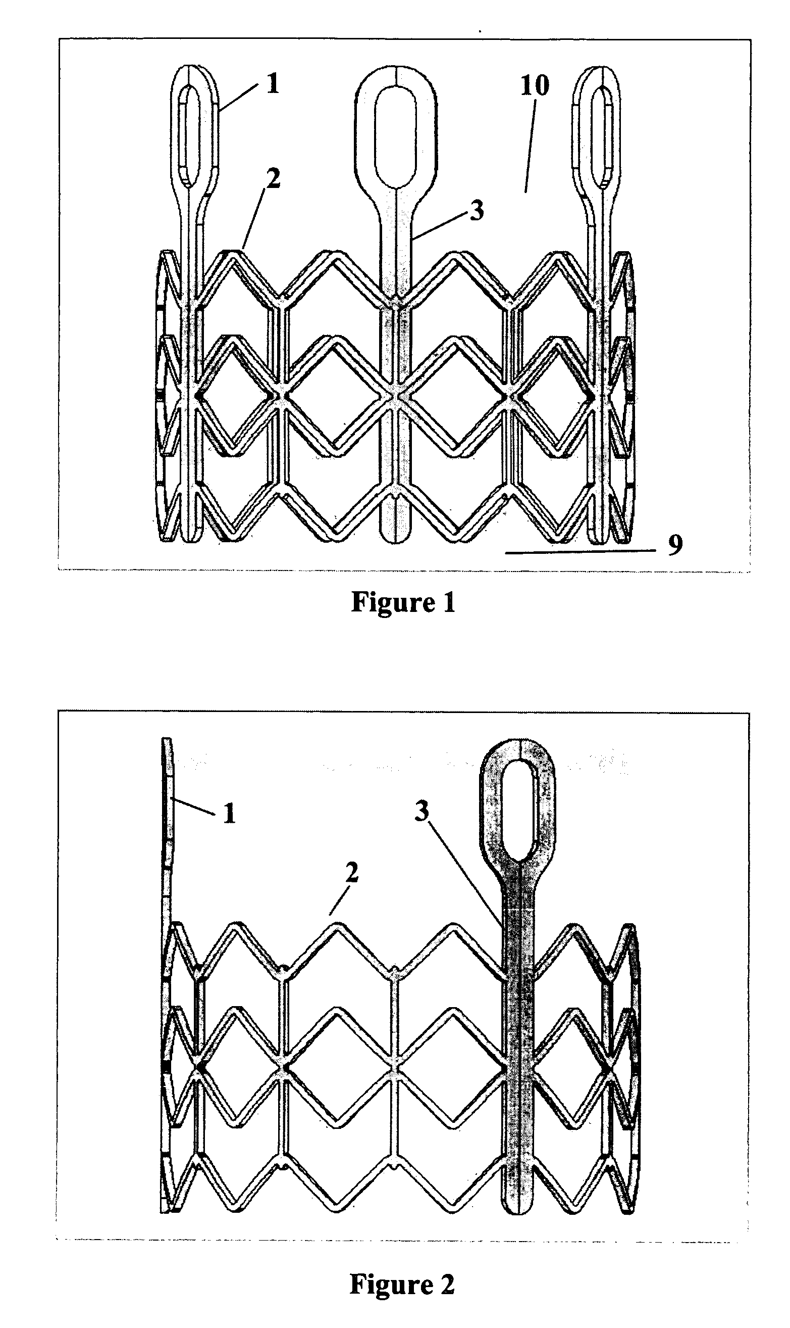
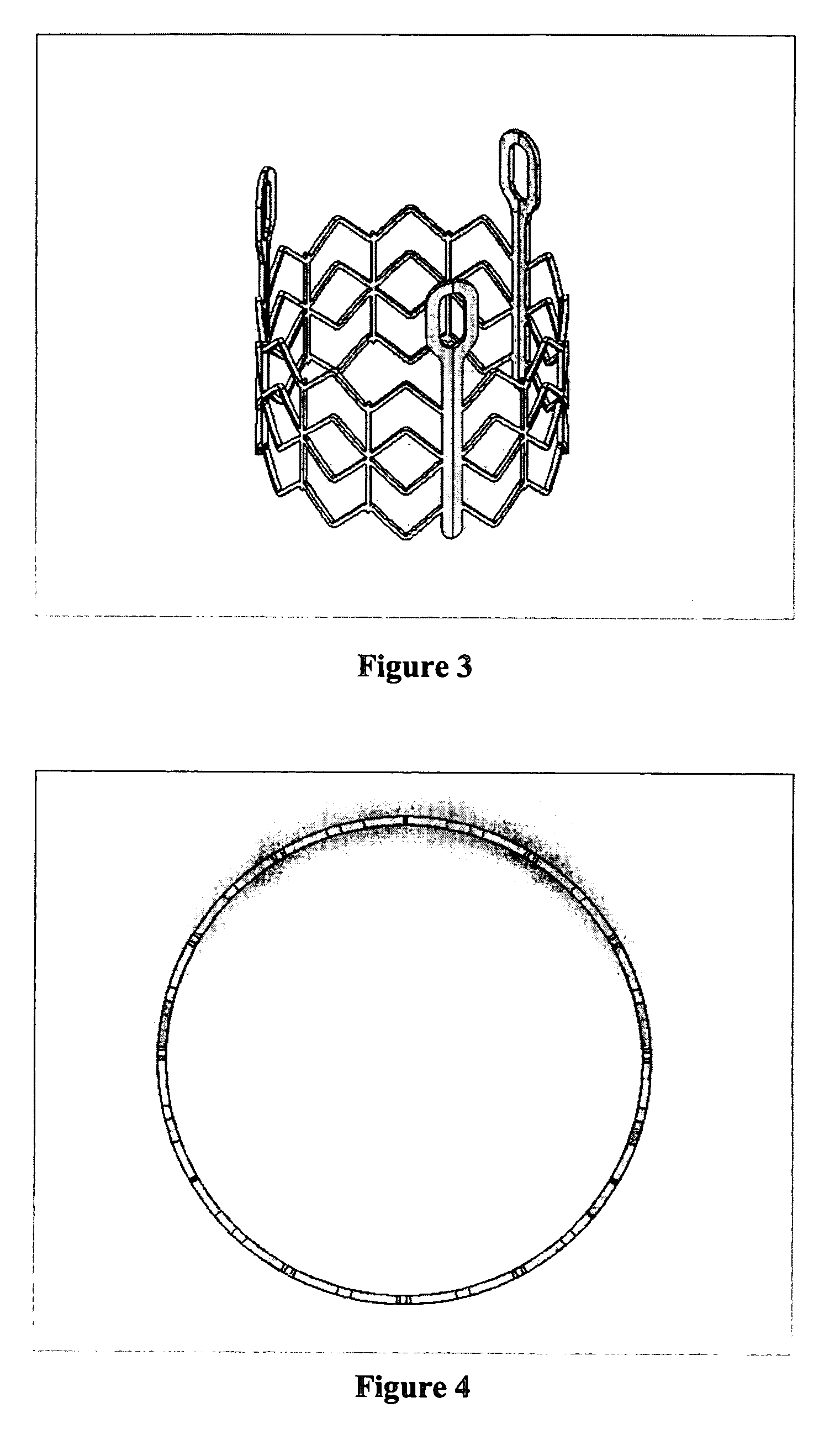
[0134] Basically the implantable prosthetic valve of the present invention comprises a leafed-valve assembly, preferably tricuspid but not limited to tricuspid valves only, consisting of a conduit having an inlet end and an outlet, made of pliant material arranged so as to present collapsible walls at the outlet. The valve assembly is mounted on a support structure such as a stent adapted to be positioned at a target location within the body duct and deploy the valve assembly by the use of deploying means, such as a balloo...


PUM


Abstract

The present invention provides valve prostheses adapted to be initially crimped in a narrow configuration suitable for catheterization through body ducts to a target location and adapted to be deployed by exerting substantially radial forces from within by means of a deployment device to a deployed state in the target location.

Description

[0001] This application claims the benefit of U.S. Provisional Application No. 60 / 565,118, filed Apr. 23, 2004.FIELD OF THE INVENTION [0002] The present invention relates to implantable devices. More specifically, the present invention relates to heart valve prosthetic devices for cardiac implantation. The present invention may also be utilized in other body cavities, vessels, or ducts. BACKGROUND OF THE INVENTION [0003] The transport of vital fluids in the human body is largely regulated by valves. Physiological valves are designed to prevent the backflow of bodily fluids, such as blood, lymph, urine, bile, etc., thereby keeping the body's fluid dynamics unidirectional for proper homeostasis. For example, venous valves maintain the upward flow of blood, particularly from the lower extremities, back toward the heart, while lymphatic valves prevent the backflow of lymph within the lymph vessels, particularly those of the limbs. [0004] Because of their common function, valves share ce...

Claims


Application Information

Patent Timeline
Patent Type & Authority Applications(United States)
IPC IPC(8): A61F2/24A61F2/04A61F2/06
CPCA61F2/2409A61F2/2418A61F2230/0054A61F2220/0075A61F2220/0041A61F2210/0014A61F2220/005A61F2230/0013A61F2230/0069A61F2250/0069A61F2250/0098A61F2/0077A61F2/04A61F2002/0086A61L27/047A61L27/18A61L27/26A61L27/3804A61L27/3882A61L27/50A61L27/507A61L2430/20
Inventor BERGHEIM, BJARNEMEYERS, KEITH E.DUMONTELLE, JEFFNGUYEN, CHRISTINE
Owner MEDTRONIC 3F THERAPEUTICS
Why Eureka
Try Eureka