Blood flow controlling apparatus

a technology of controlling apparatus and flow, applied in the field of blood flow control apparatus, can solve the problems of leakage of valve valve, high risk of open heart surgery, and very common heart valve diseas

Inactive Publication Date: 2006-10-26
EDWARDS LIFESCIENCES AG
View PDF57 Cites 922 Cited by
  • Summary
  • Abstract
  • Description
  • Claims
  • Application Information

AI Technical Summary

Benefits of technology

[0030] In another embodiment, the valve means comprises several flaps. The flaps may overlap each other to properly seal the valve or vessel when extending to make contact with the native valve leaflet or the vessel wall. Thus, no backflow is allowed between the flaps. As an alternative, adjacent flaps may tightly contact each other to prevent leakage between the flaps.
[0031] The flaps may be strengthened at an end which is attached to the connecting means. The strengthened base may act to prevent the flaps from turning over.

Problems solved by technology

Heart valve disease is a very common problem.
To certain groups of patients, open-heart surgery is particularly hazardous.
Thus, an existing gap or incomplete area of coaptation between the leaflets creates a leak in the valve.
However, the described method is only useful in diseased valves where the reason for a valvular leak is caused by a dilation of the valve annulus.
In cases where these methods are not useful, the valve may need to be replaced.
However, the stented valves are only useful in circular orifices such as the pulmonary and the aortic valves.
If the known stented valves with round circumference are introduced into the oval mitral annulus with a leaking area of slit-like shape, there will be wide open areas causing a severe leak, so called paravalvular leak, between the implanted device and the annulus.
In addition, the tissue is too weak to allow a good fixation in the tricuspid and mitral orifices.
Further, if a known stented valve is introduced in the mitral valve orifice, it would also create a block in the outflow of the aortic valve.
The known stented valves also have limitations in use for the pulmonary valve.
The known stented valves are not suited to be implanted in children or growing juveniles, since they do not permit growths of the valve annulus.
However, the most severe drawback with the known stented valves is the size of the device when mounted in delivery systems before implant.

Method used


Image

  • Blood flow controlling apparatus
  • Blood flow controlling apparatus
  • Blood flow controlling apparatus

Examples


first embodiment

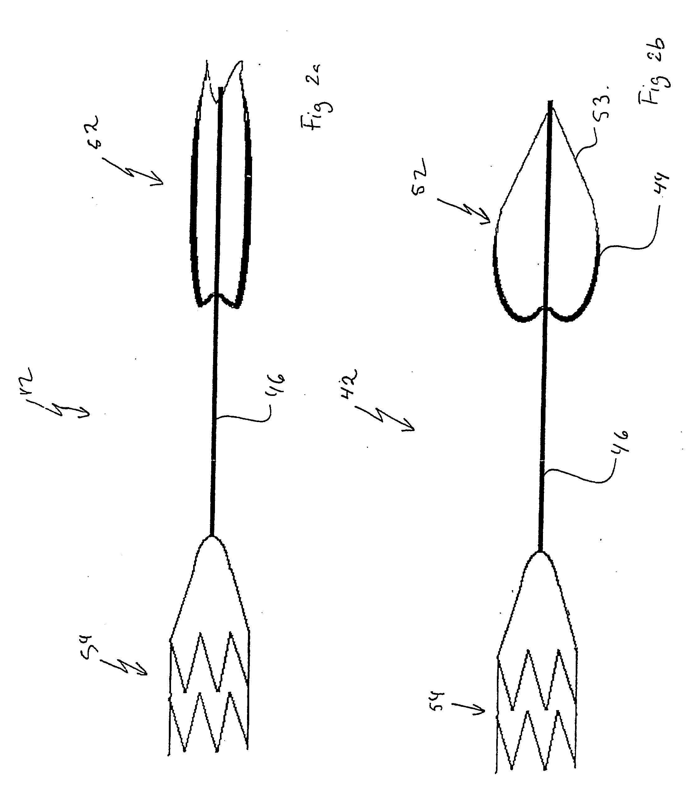
[0105] shown in FIG. 6a, the valve means 52 comprises a flap 44 which symmetrically encircles the connecting means 46. The flap 44 is attached to the connecting means 46 around its entire circumference in a longitudinal attachment point 90 forming a fluidtight attachment around the connecting means 46. The flap 44 is hinged in the attachment point 90 such that it is moveable between an open position where it extends mainly along the connecting means 46 and a closed position, as shown in FIG. 6a, where it extends in a mainly transverse direction to the connecting means 46. The flap 44 has a contact surface 92 which faces the forward flow in the native heart valve or the vessel and which is arranged to contact the leaflets of the native heart valve or the vessel wall in the closed position of the flap 44. When moving into the closed position, the flap 44 will move towards increasingly extending in a transverse direction to the connecting means 46. The contact surface 92 will then com...

third embodiment

[0109] In the third embodiment shown in FIG. 6c, the valve means 252 comprises several flaps 244. The flaps 244 are attached to a common attachment position 290 around the connecting means 46. Each flap 244 has a contact surface 292 with a coaptation area 294 and the flap 244 is moveable to put the coaptation area 294 of the contact surface 292 in contact with the leaflets of the native heart valve or the vessel wall. The flaps 244 are broadening towards the coaptation area 294. Further, the flaps 244 are overlapping and arranged as the leaves of a hibiscus flower so as to form a tight seal between them when extending to make contact with the heart valve or the vessel wall. The flaps 244 further have a strengthened base 296 close to the attachment position 290. The strengthened base 296 will prevent the flap 244 from turning over due to backflow in the heart valve or the vessel.

fourth embodiment

[0110] In the fourth embodiment shown in FIGS. 7a-d, the valve means 352 comprises several flaps 344 which are arranged side-by-side encircling the connecting means 46. As indicated in FIG. 7c showing a perspective view of the valve means 352, each flap 344 comprises a contact surface 392 with a coaptation area 394. The flaps 344 are wedge-formed with the narrow end towards the connecting means 46 and the broad end arranged to make contact with the native heart valve or the vessel wall. As indicated in FIG. 7a showing a cross section of the valve means 352 when inserted in a native heart valve or a vessel, adjacent flaps 344 extend along each other and are arranged close together such that adjacent surfaces present respective coaptation areas 392, which will be in close contact with each other to prevent leakage between the flaps 344. In FIG. 7a, the valve means 352 is depicted in the closed position in which it is arranged to make contact with the native heart valve or a vessel wal...


PUM


Abstract

A blood flow controlling apparatus, which is configured to be implanted into a blood circulatory system of a patient, comprises an anchoring means, which is arranged to fix the position of the apparatus in the blood circulatory system, and a valve means being connected to the anchoring means. The valve means is configured to be arranged within the blood circulatory system and is configured to be extendable in a direction transverse to blood flow in order to make contact with native tissue when inserted in the blood circulatory system. The valve means is further configured to release said contact as a result of being exposed to blood flow in a permitted direction.

Description

CROSS REFERENCE TO A RELATED PATENT APPLICATION [0001] The present application claims priority to Swedish Patent Application Serial No. 0500891-7, filed on Apr. 21, 2005, the disclosure of which is incorporated by reference herein in its entirety. TECHNICAL FIELD [0002] The present invention relates to a blood flow controlling apparatus, which is configured to be implanted into a blood circulatory system of a patient, and to a method for treatment of leaking heart valves. BACKGROUND OF THE INVENTION [0003] Heart valve disease is a very common problem. Each year, half a million people in the world develop heart valve disease. 200,000 are too sick to be treated, but the rest are treated. At present, the treatment of heart valve disease consists of either heart valve repair or valve replacements. Both methods require open-heart surgery, by the use of total cardiopulmonary by-pass, aortic cross-clamping and arrest of the heart. To certain groups of patients, open-heart surgery is partic...

Claims


Application Information

Patent Timeline
Patent Type & Authority Applications(United States)
IPC IPC(8): A61F2/24
CPCA61B2017/0412A61F2/2418A61F2/246A61F2/2466A61F2/2442A61F2220/0008A61F2220/0016A61F2230/0054A61F2/2403A61F2/2412A61F2210/0014A61F2310/00017A61F2310/00023A61F2/2427A61F2/2457
Inventor SOLEM, JAN OTTO
Owner EDWARDS LIFESCIENCES AG
Why Eureka
Try Eureka