Long packaging material for manufacturing pouch

a packaging material and pouch technology, applied in the field of elongated packaging material for manufacturing pouches, can solve the problems of inability to distinguish from other products in adequate ways, unsuitable for improving productivity, and less speed of described manufacturing methods of pouches, so as to achieve efficient and sanitarian manufacturing

Inactive Publication Date: 2011-05-31
FUJI SEAL INTERNATIONAL INC
View PDF20 Cites 14 Cited by
  • Summary
  • Abstract
  • Description
  • Claims
  • Application Information

AI Technical Summary

Benefits of technology

[0013]The present invention has been proposed under the above-described circumstances. It is therefore an object of the present invention to provide an art for efficiently and sanitarily manufacturing pouches having a narrow portion.
[0016]According to the present invention, the long packaging material is cut into the sets, each including a pair of sheets, so that a plurality of pouch bodies (or pouches made of the pouch bodies) are successively manufactured. Each of the pouch bodies includes side ends sealed by the side sealing portions, a bottom sealed by the cross sealing portion, and an opening at its top. As each of the side sealing portions is provided with a projecting portion projecting toward the center of the width of the sheet, the outside of the projecting portion can be cut out, widthwise thereof, to form a recess. Thus, each of the pouch bodies is provided with an arrow portion, widthwise thereof, and the narrow portion is properly sealed. In this way, the long packaging material according to the present invention can be used to properly manufacture a plurality of pouch bodies (or pouches) each having a peculiar form, which is the object of the invention. Further, in the present invention, following effect can be obtained.
[0018]Second, in manufacturing pouches by cutting the long packaging material for manufacturing pouch according to the present invention, the long packaging material is rolled in advance, for example, successively pulled out from the roll to be transferred through a predetermined transfer path, and cut at a predetermined position. At this cutting position, a plurality of pouch bodies are made and supplied one by one. The pouch bodies are immediately transferred for the next process one by one, so that desired products containing e.g. beverage can be manufactured quickly. This manufacturing method can reduce the cost, as there is no need to use a complicated machine, in which, for example, a plurality of the pouch bodies are piled up and accurately pulled out one by one.
[0019]Third, when transferring the long packaging material to the cutting position, its posture during the transfer can be stable, differing from transferring the single pouch body. As described above, it is difficult to guide the single pouch body having an arrow portion widthwise thereof, in transferring one by one, and its position may be disadvantageously changed. However, in the present invention, even if the long packaging material is formed with a plurality of narrow portions, portions other than the narrow portions can be guided to prevent the long packaging material from snaking, to be properly transferred.
[0020]Fourth, in the present invention, the long packaging material is strengthened and thus prevented from being warped or wrinkled during transfer. Specifically, as the projecting portions, provided at the side sealing portions, project toward the center of the width of the sheets, the sheets are strengthened to be rigid. At the projecting portions of the side sealing portion, the sheets are partly layered and contacting to each other, and thus stiffer and more rigid than other portions of the sheets other than the sealing portions, thereby obtaining the above effect. Therefore, in the present invention, when manufacturing pouches by pulling out the long packaging material from the roll, the transfer process can be facilitated. Further, without the warp and wrinkle, labeling or printing process can be performed efficiently on the transfer path.
[0021]Preferably, each of the first and second sheets is formed with recesses, outside of the projecting portions, widthwise of the sheet. Due to this structure, a pouch body can be formed with a narrow portion, widthwise thereof, by only cutting the sheets widthwise, which facilitates the manufacturing operation. Further, by forming a plurality of cutouts or recesses at the sheets, entire weight of the long packaging material can be reduced, and thus the distribution cost is reduced.

Problems solved by technology

Further, because of the similar forms, distinction from other products cannot be made adequately.
First, each pouch body P′ includes an opening at its top. Thus, in storage or transfer of the pouch body P′, dust may come into a pouch body P′ through the opening.
Second, it is not always easy to accurately set a plurality of flexible pouch bodies P′ to the supplying magazine. Further, it is not a very efficient operation to accurately pick out pouch bodies P′ one by one from the set position for transferring each of them to the next process. Thus, the above-described manufacturing method of pouches is less speedy and unsuitable for improving productivity. Further, the system for such manufacturing method is complicated and thus the cost is expensive.
Third, when transferring a pouch body P′ by the conveyor, the pouch body P′ may change its posture due to vibration of the transfer machine. As the pouch body P′ has a narrow portion at the intermediate part in the height, it is difficult to properly guide its sides. If the posture of the pouch body P′ is not stable during transfer, the operation at the next process may not be performed properly.

Method used


Image

  • Long packaging material for manufacturing pouch
  • Long packaging material for manufacturing pouch
  • Long packaging material for manufacturing pouch

Examples


first embodiment

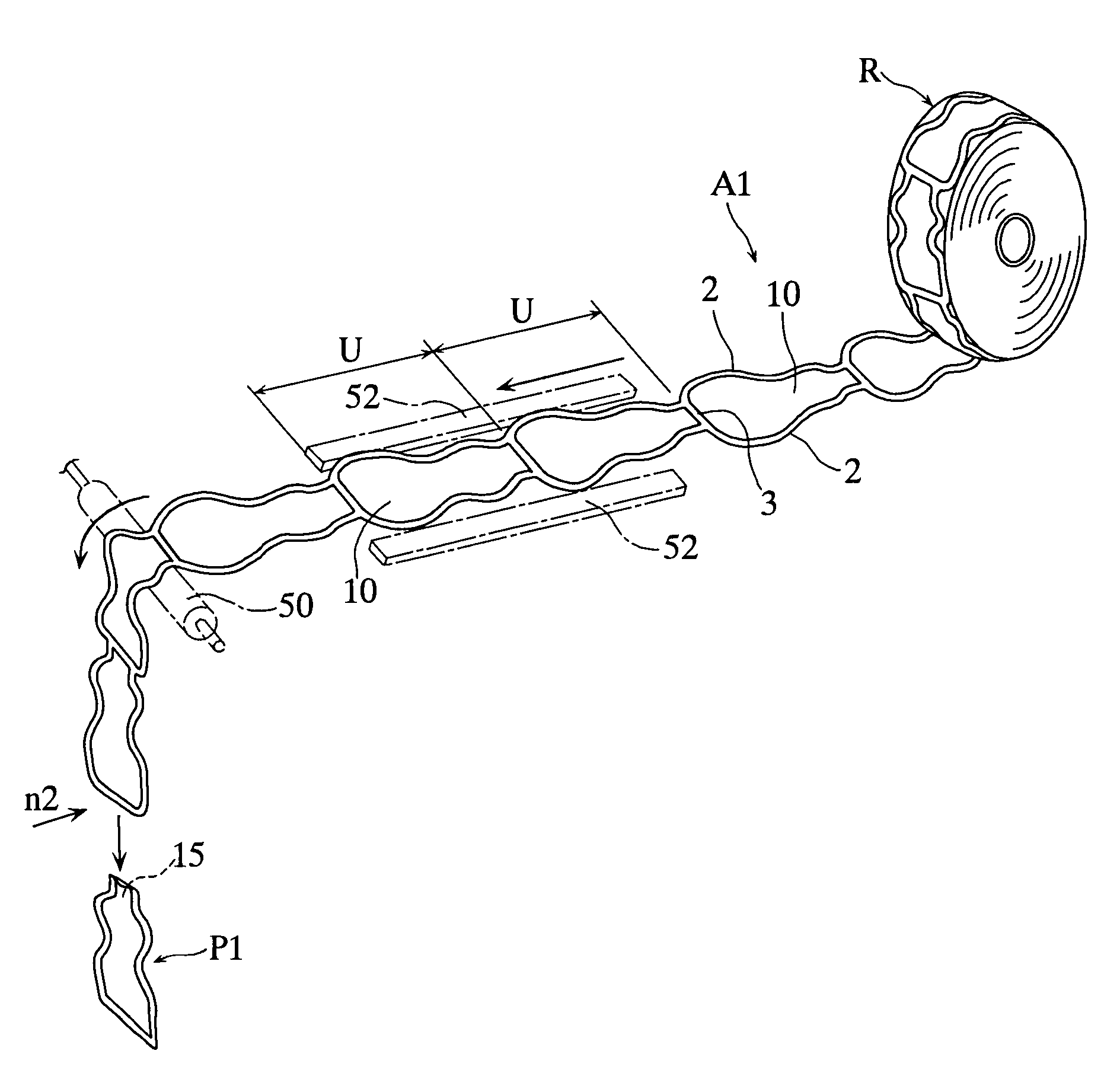
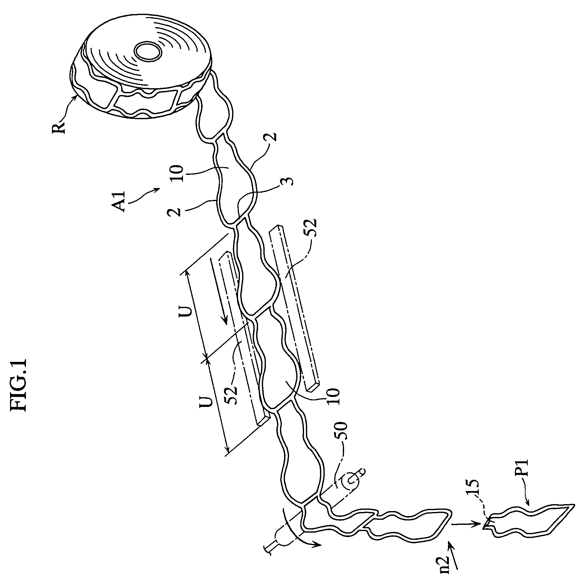
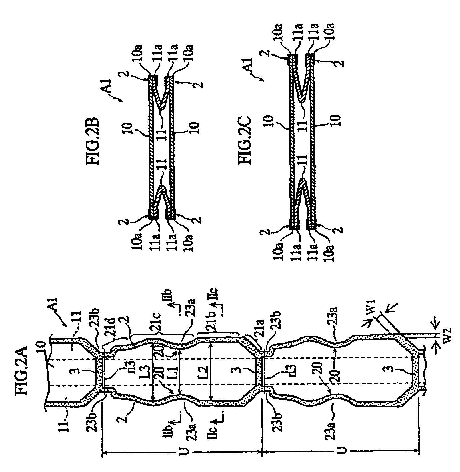
[0035]FIGS. 1 and 2A-2C illustrate a long packaging material for manufacturing pouch according to the present invention. As shown in FIGS. 2B and 2C, a long packaging material A1 includes a pair of sheets 10 and a pair of gussets 11 provided between the sheets. The two sheets 10 are connected to each other via the two gussets 11. Connecting portions (side sealing portions) of the sheets 10 and the gussets 11 are indicated by a reference number 2. A reference number 3 in FIGS. 1 and 2A indicates cross sealing portions.

[0036]The pair of sheets 10 are elongated in a same direction and laminated on each other in the thicknesswise direction. Each gusset 11 is bent into a V-shape in section, and elongated in the same direction as the sheets 10 are elongated. Each of the sheets 10 and the gussets 11 may be a laminated film made by laminating one or more layers of resin film on surfaces of an aluminum film. A resin film of the laminated film that serves as the outermost layer of the long pa...

second embodiment

[0052]As shown in FIG. 5A, along packaging material A2 includes side sealing portions 2, each having a plurality of linear portions 16a and curved portions 16b alternately aligned lengthwise of the long packaging material A2. The curved portions 16b form projecting portions 20 projecting toward the center of the width of the long packaging material A2. Each of the cross sealing portions 3 is linearly elongated widthwise of the long packaging material A2, and includes bent ends each connected to a respective one of the side sealing portions 2. The sheets 10 and the gussets 11 are formed with cutouts or recesses 23a, outside and widthwise of the projecting portions 20. Thus, the sheets 10 and the gussets 11 are formed with narrow portions, and have a constant width except at the narrow portions.

[0053]As shown in FIG. 5B, when the long packaging material A2 is cut at the portions indicated by reference numbers n5, n6, extra pieces 60a are obtained in addition to pouch bodies P2 each h...


PUM

PropertyMeasurementUnit
areaaaaaaaaaaa
lengthaaaaaaaaaa
flexibleaaaaaaaaaa

Abstract

An elongated packaging material (A1) for manufacturing a pouch comprises a first elongated flexible sheet (10), and a second elongated flexible sheet (10) layered on the first sheet. The side ends of the first and the second sheets are provided with a plurality of side sealing portions (2) extending lengthwise of the sheets. A plurality of cross sealing portions (3) are spaced from each other lengthwise of the sheets. Each of the side sealing portions is provided with a plurality of projecting portions (20), each projecting toward a center of the width of the sheets, between an adjacent pair of cross sealing portions.

Description

TECHNICAL FIELD[0001]The present invention relates to an elongated packaging material for manufacturing pouch for containing a beverage or a jelly-type food, for example.BACKGROUND ART[0002]Examples of pouches for containing a beverage include various conventional pouches. Specifically, a pouch with a spout is disclosed in the following patent document 1 or 2.[0003]Patent Document 1: JP-A-H10-202768[0004]Patent Document 2: JP-A-2001-9744437[0005]As shown in FIG. 11, a conventional pouch with a spout includes a pouch body made of a pair of flexible sheets 7 and also includes a spout 51 inserted into the pouch body. A reference character 70A indicates a heat sealing portion formed at the side ends and the bottom of the pouch body. A reference character 70B indicates a heat sealing portion formed at the top of the pouch body. By forming the heat sealing portion 70B, an opening at the top of the pouch body is closed and the spout 51 is fixed to the pouch body.[0006]In the above-describe...

Claims


Application Information

Patent Timeline
Patent Type & Authority Patents(United States)
IPC IPC(8): B65D30/00B65D30/20B31B19/36B31B19/84B31B23/00B65D30/10B65D75/42B65D75/58
CPCB31B19/36B31B19/84B31B23/00B65D75/42B65D75/44B65D75/5883B31B2219/2627B31B2219/269B65D2575/583B31B2237/10B31B2237/50B31B2219/9054Y10S383/907B31B70/00B31B2160/10B31B70/36B31B2155/00B31B70/266B31B70/844B31B2155/002
Inventor FUKUIZUMI, TAKASHI
Owner FUJI SEAL INTERNATIONAL INC
Why Eureka
Try Eureka