Assembly for setting a valve prosthesis in a corporeal duct

a valve prosthesis and corporeal duct technology, which is applied in the direction of prosthesis, surgical staples, blood vessels, etc., can solve the problems of limiting the expansion force that it is possible to give to the stent, damage to the corporeal duct, and risk of valve damage, so as to eliminate any risk of covering the coronary ostia

Inactive Publication Date: 2005-02-10
MEDTRONIC COREVALVE
View PDF82 Cites 886 Cited by
  • Summary
  • Abstract
  • Description
  • Claims
  • Application Information

AI Technical Summary

Benefits of technology

[0018] Each elongated reinforcing element advantageously presents a curved form and is placed with its convex side radially turned toward the inside of the support, so that this support presents, at its median zone, a smaller diameter compared to the diameter that it presents at its axial extremities. This smaller diameter allows any risk of covering the coronary ostia to be eliminated.
[0019] In an alternative embodiment of the invention, the support comprises two tubular portions, such as that described above, whereby one of the extremities of the elongated reinforcing elements is linked to one of these tubular portions while the other extremity of these elongated reinforcing elements is linked to the other tubular portion. The extension of these two tubular portions ensures a perfect extension of the elongated reinforcing elements.

Problems solved by technology

However, this technique may have important disadvantages leading to a risk of damage to the valve by the balloon utilized for expanding the stent, and limiting the expansion force that it is possible to give to the stent.
This limitation has an effect on the anchoring of the stent, making a displacement of the assembly possible.
This limitation also has an effect on the sealing of the stent at the valvular ring, which is particularly affected when the calcified areas give the valvular ring an irregular form and / or a certain rigidity.
Expansion of the balloon may also lead to damage to the corporeal duct, particularly when the duct is in a blood vessel.
Furthermore, the target corporeal duct may not present a perfectly circular cross section at the implantation site, particularly when the natural valve is retained and when this valve, or valvular ring, comprises calcified areas.
Whatever the degree of expansion of the stent, the circular shape of this stent then may not be suitable for the specific anatomy of the implantation site.
A defect in sealing of the implanted valve may then result.
Furthermore, the stent presents a certain rigidity, which leads to a rigidity in the implantation catheter.
This rigidity may make the advancement of this catheter to the implantation site difficult.
Another disadvantage of the prior technique is the direct connection of the leaflets' commissures to the stent.
A different than anticipated expansion of the stent, and thus of the valve, results, which may lead to a poor coaptation of the leaflets and thus a defective operation of the valve.
The prior technique also has the disadvantage of, in cases of aortic valve implantation, inducing a risk of obstruction of the coronary ostia.

Method used


Image

  • Assembly for setting a valve prosthesis in a corporeal duct
  • Assembly for setting a valve prosthesis in a corporeal duct
  • Assembly for setting a valve prosthesis in a corporeal duct

Examples


Embodiment Construction

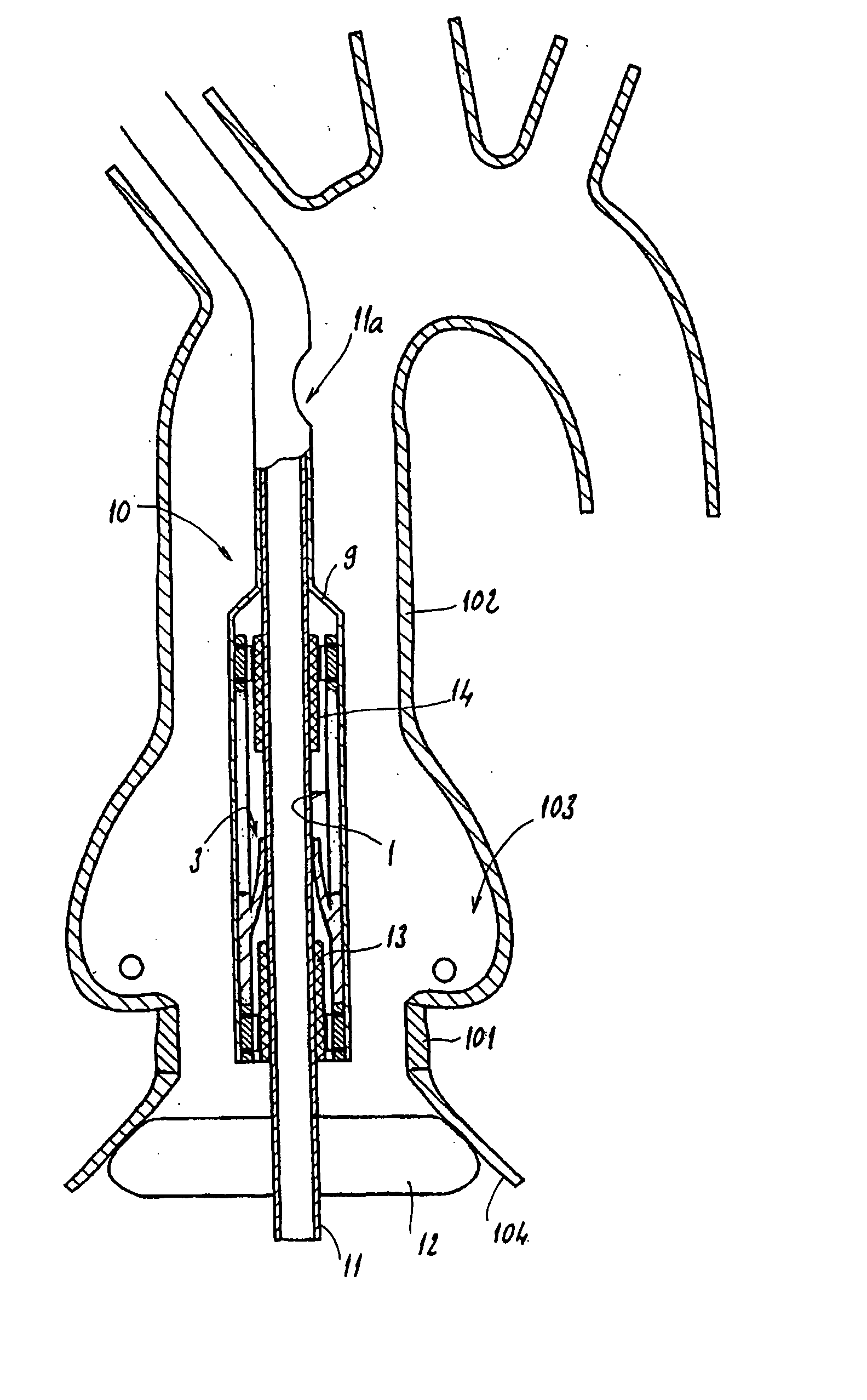
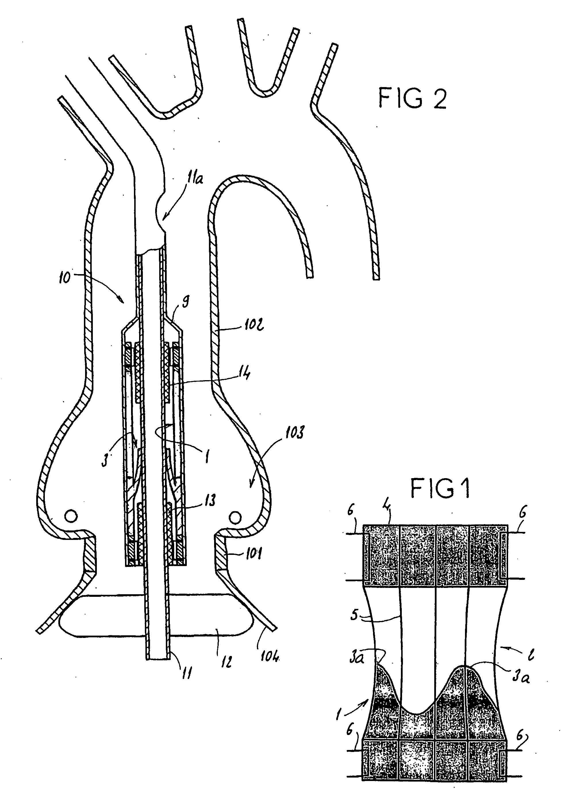
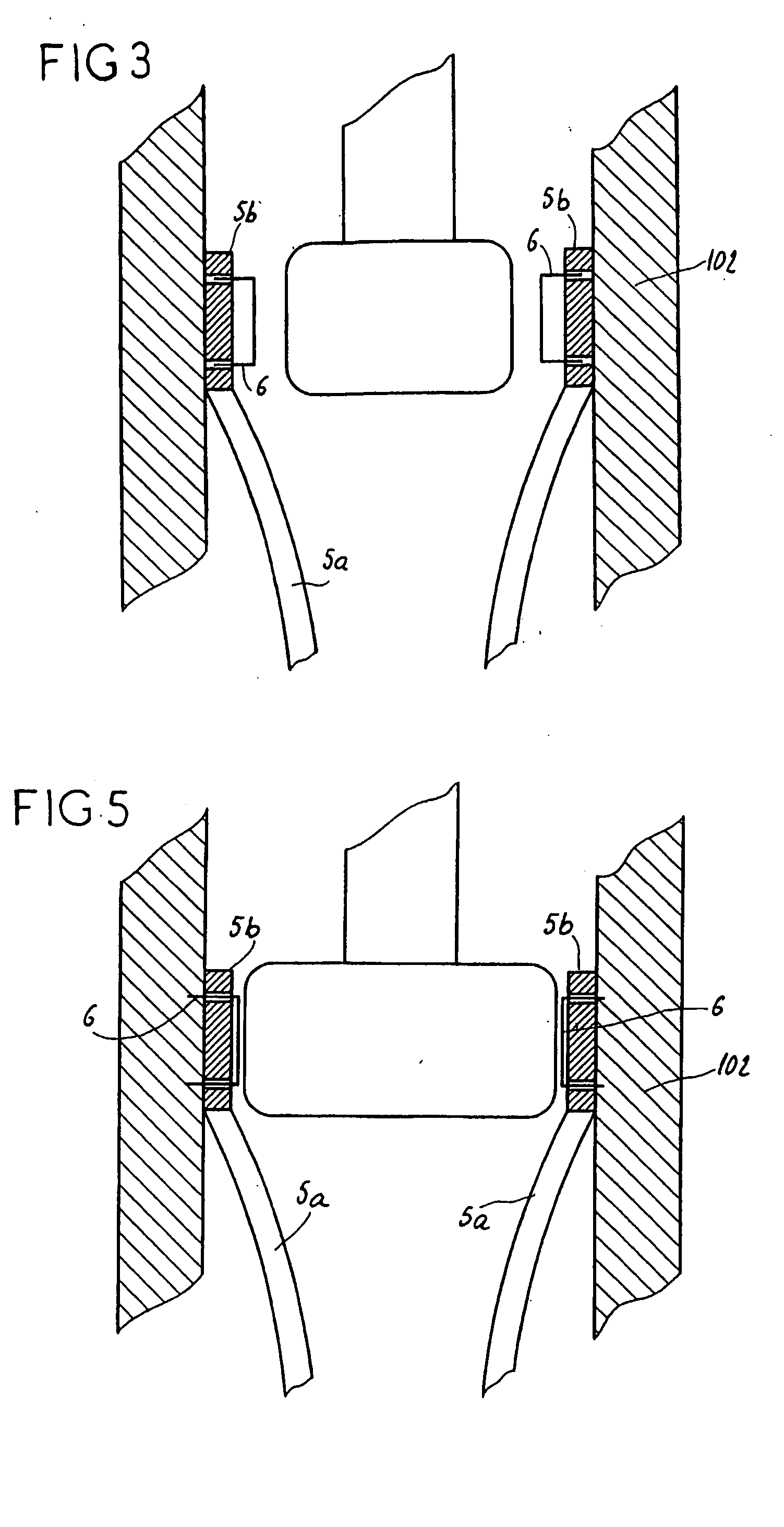
[0043] Referring to FIG. 1, the present invention comprises a prosthetic valve assembly 1. The assembly 1 comprises a support 2 on which is mounted a valve prosthesis 3, which in one embodiment is an aortic valve. The support 2 preferably comprises a distal and proximal tubular portion 4 separated by a plurality of elongated reinforcing elements 5. The tubular portions 4 are preferably made of a pliable material that is slightly stretchable in the circumferential direction of these tubular portions 4. In particular, the tubular portions may be constructed of a polymer or of a fiber fabric known under the name “dacron,” or even in a biological tissue like the pericardium. The diameter of these tubular portions 4 should preferably correspond to the diameter of the target native lumen, for example, the aorta, as shown in FIGS. 2 and 4, where the native valve ring 101, the wall 102 of the aorta, and the coronary ostia 103, are shown.

[0044] Each elongated reinforcing element 5 is constr...


PUM


Abstract

The invention concerns an assembly comprising a valve prosthesis to be implanted and a support receiving said valve. The support comprises: at least a tubular portion made of a pliable material slightly stretchable in the circumferential direction; means for fixing said tubular portion to the wall of the corporeal duct; and a plurality of elongated reinforcing elements, arranged on the circumference of said tubular portion and linked to said tubular portion independently of one another; the valve is linked at least partly to said elongated reinforcing elements, in particular at the commissures of its leaflets, and said elongated reinforcing elements jointly form, in extended position, a structure having a predetermined diameter that ensures sufficient extension of said valve.

Description

CROSS-REFERENCE TO RELATED APPLICATIONS [0001] The present application is the U.S. national phase under § 371 of International Application No. PCT / FR02 / 02745, filed on Jul. 31, 2002, which was published in a language other than English and which claimed priority from French Application No. 01 / 10281, filed on Jul. 30, 2001.BACKGROUND OF THE INVENTION [0002] 1. Field of the Invention [0003] The present invention relates to an assembly for setting a valve prosthesis in a corporeal duct, especially a cardiac valve and in particular an aortic valve. [0004] 2. Description of the Related Art [0005] Documents WO 91 / 17720, WO 98 / 29057 and EP 1 057 460 each describe an assembly of this type, comprising the valve prosthesis to implant; a radially expandable reinforcement, called a “stent,” clean, in the expanded state, to bear against the wall of the target corporeal duct, this bearing allowing this stent to be immobilized with respect to this wall; and means for fixing the valve to the stent....

Claims


Application Information

Patent Timeline
Patent Type & Authority Applications(United States)
IPC IPC(8): A61B17/00A61B17/064A61B17/068A61B17/072A61B17/115A61F2/24
CPCA61B17/0644A61B17/068A61B17/072A61B17/115A61F2230/0078A61B2017/00557A61F2/2418A61F2/2433A61F2220/0016A61B17/1155
Inventor SEGUIN, JACQUES
Owner MEDTRONIC COREVALVE
Why Eureka
Try Eureka