Kit enabling a prosthetic valve to be placed in a body enabling a prosthetic valve to be put into place in a duct in the body

a prosthetic valve and kit technology, applied in the field of aortic valves, can solve the problems of reducing the leakage of the stent in the area, reducing the expansion force of the stent, and reducing the leakage of the stent, so as to reduce the risk of valve damag

Inactive Publication Date: 2005-02-24
MEDTRONIC ARDIAN LUXEMBOURG SARL
View PDF74 Cites 864 Cited by
  • Summary
  • Abstract
  • Description
  • Claims
  • Application Information

AI Technical Summary

Benefits of technology

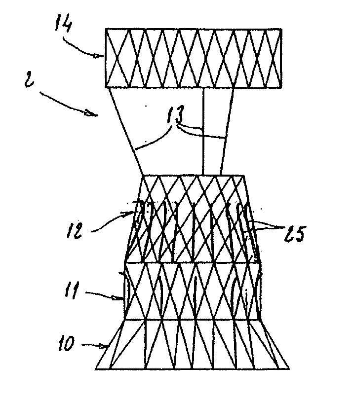
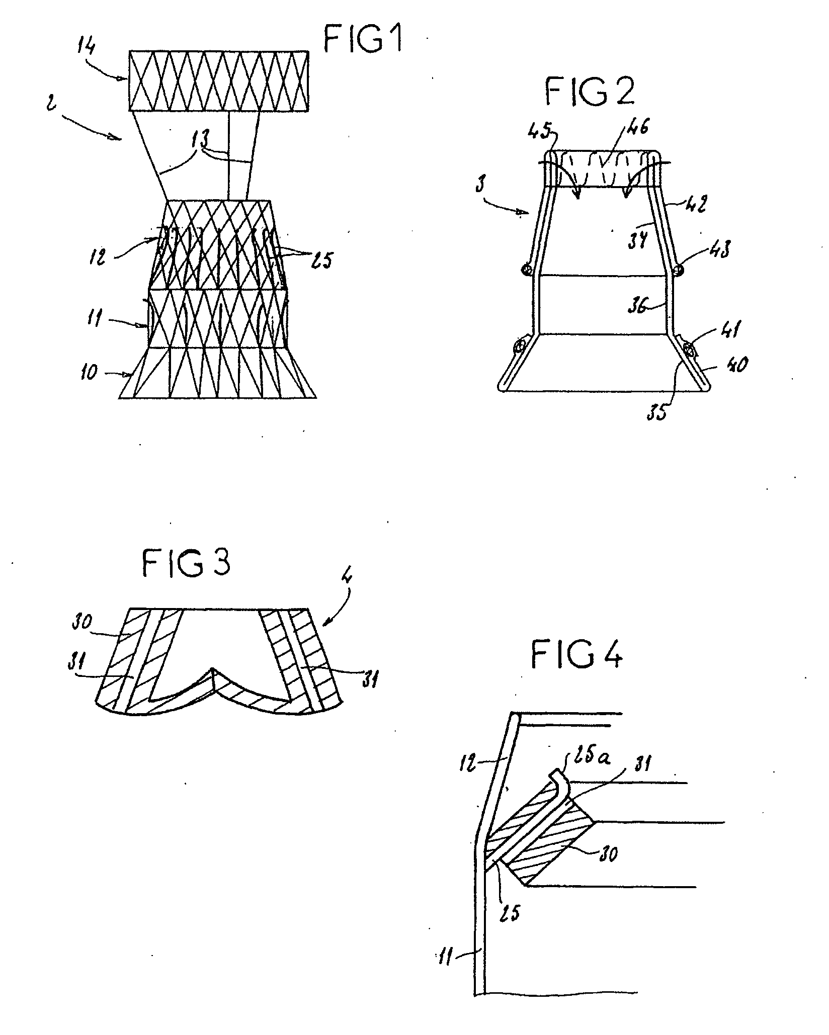
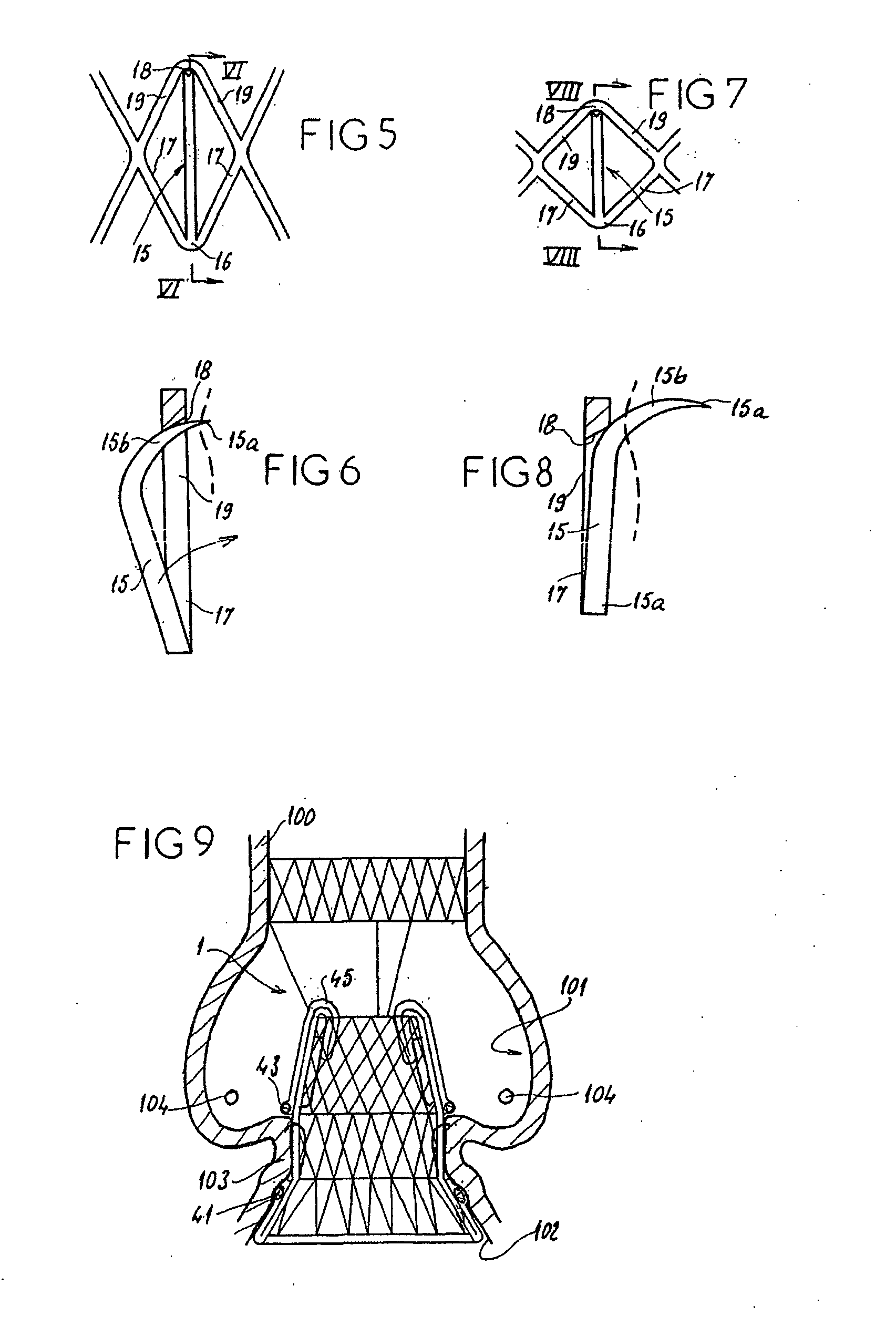
[0009] The present invention aims to overcome these various drawbacks. The assembly of the present invention comprises a prosthetic valve to be implanted; a radially expandable framework, or stent, comprising at least one zone intended to be expanded to allow the stent, in the expanded state, to bear against the wall of the body duct to be fitted with the valve, this bearing making it possible to immobilize the stent with respect to this wall; and means for mounting the valve with respect to the stent, making it possible to connect the valve to the stent in such a way that the placement of the stent allows the valve to be mounted in the body duct, and expansion means such as a balloon catheter being provided to trigger expansion of the stent at the implantation site. According to the invention, the valve and the stent are designed in such a way that, at the moment when the stent is expanded, the valve is situated outside the zone or zones of the stent that are subjected to said expansion means. The invention thus consists in separating the valve and said zone or zones to be expanded, so that the expansion of the stent can be effected with an expansion force suitable for perfect anchoring of this stent in the wall of the body duct to be fitted with the valve, and without any risk of destruction or damage of the valve.

Problems solved by technology

However, major drawbacks of this technique are that it entails a risk of the valve being damaged by the balloon used to expand the stent, and it limits the force of expansion that can be imparted to the stent.
This limitation has repercussions on the anchoring of the stent, making a displacement of said assembly possible.
This limitation also has repercussions on the leaktightness of the stent in the area of the valvular ring which is particularly affected when calcified zones give the valvular ring an irregular form and / or a certain rigidity.
Another drawback of the prior art technique is that of directly joining the commissures of the valvules to the stent.
The result of this is that an expansion of the stent, and thus of the valve, different than that intended may cause poor coaptation of the valvules and, consequently, defective functioning of the valve.
In the case of implantation of an aortic valve, the prior art technique also has drawbacks in that it necessitates very exact positioning of the stent in the aorta so that the valve is located opposite the natural valvular ring, and it entails a risk of blocking the apertures of the coronary arteries that open out at the coronary ostia.

Method used


Image

  • Kit enabling a prosthetic valve to be placed in a body enabling a prosthetic valve to be put into place in a duct in the body
  • Kit enabling a prosthetic valve to be placed in a body enabling a prosthetic valve to be put into place in a duct in the body
  • Kit enabling a prosthetic valve to be placed in a body enabling a prosthetic valve to be put into place in a duct in the body

Examples


second embodiment

[0065] In the assembly 1, the valve 4 is not mounted in advance inside the stent 2 but is placed in it once the stent 2 has been expanded. As is shown in FIG. 10, the sheath 3 then has internal tubes 50 formed in such a way as to protrude inside the stent 2 once this sheath 3 is engaged on the stent 2. These tubes 50 can in particular be sewn or fixed by any other means to the sheath 3 after the latter has ben placed on the stent 2.

[0066] Referring to FIG. 11, it will be seen that the peripheral wall 30 of the valve 4 has, in place of the tunnels 31, a series of pin-shaped clips 51. Each clip 51 has an inner arm 52 engaged longitudinally in the wall 30, and a rectilinear outer arm 53 extending along the outer face of the wall 30. The arms 53 terminate in curved ends and are connected to wires 55 engaged and able to slide in the tubes 50.

[0067] As is shown in FIG. 10, a catheter 80 is used to bring the valve 4 into position in the sheath 3. The valve 4 is engaged with sliding on the...

third embodiment

[0068] In the assembly 1 shown in FIG. 13, the stent 2 forms a median cage delimited by a ring 60 and by longitudinal wires 61, in which cage the valve 4 is tightly inserted. As is shown in FIG. 14, the valve 4 has a lateral wall 30 of tubular shape in which three lateral openings 65 are formed. These openings 65 are positioned opposite the coronary ostia 101 and permit a natural flow of blood, without risk of stagnation in the area of these coronary ostia 101.

[0069] The invention provides an assembly 1 for placing a valve 4 in a body duct 100, said assembly having the following advantages over similar assemblies in the prior art: elimination of the risk of damage to the valve 4 by the balloon or balloons used to expand the stent 2; possibility of applying a considerable force of expansion to the stent 2, that ensures the anchoring of the assembly 1; this considerable force of expansion additionally permits this anchoring by means of the deployable hooks 15; elimination of the risk ...


PUM


Abstract

The present invention is an assembly comprising a prosthetic valve to be implanted; a radially expandable stent comprising at least one zone intended to be expanded to allow the stent, in the expanded state, to bear against the wall of the body duct to be fitted with the valve, this bearing making it possible to immobilize this stent with respect to this wall; and means for mounting the valve with respect to the stent, making it possible to connect the valve to the stent in such a way that the placement of the stent allows the valve to be mounted in the body duct, and expansion means such as a balloon catheter being provided to trigger expansion of the stent at the implantation site. According to the invention, the valve and the stent are designed in such a way that, at the moment when the stent is expanded, the valve is situated outside the zone or zones of the stent that are subjected to said expansion means. The invention thus consists in separating the valve and said zone or zones to be expanded, so that the expansion of the stent can be effected with an expansion force suitable for perfect anchoring of this stent in the wall of the body duct to be fitted with the valve, and without any risk of destruction or damage of the valve.

Description

CROSS-REFERENCE TO RELATED APPLICATIONS [0001] The present application is the U.S. national phase under § 371 of International Application No. PCT / FR02 / 02352, filed on Jul. 4, 2002, which was published in a language other than English and which claimed priority from French Application No. 01 / 08898, filed on Jul. 4, 2001.BACKGROUND OF THE INVENTION [0002] 1. Field of the Invention [0003] The present invention relates to an assembly for placing a prosthetic valve in a lumen of the body, especially a heart valve, and in particular an aortic valve. [0004] 2. Description of the Related Art [0005] Documents WO 91 / 17720, WO 98 / 29057 and EP 1 057 460 each describe an assembly, including the prosthetic valve to be implanted; a radially expandable framework, called a stent, which is able, in the expanded state, to bear against the wall of the body duct to be fitted with the valve, this bearing making it possible to immobilize this stent with respect to this wall; and means for fixing the valv...

Claims


Application Information

Patent Timeline
Patent Type & Authority Applications(United States)
IPC IPC(8): A61F2/24
CPCA61F2/2403A61F2/2418A61F2220/0016A61F2230/0067A61F2220/0008A61F2220/005A61F2250/006
Inventor SEGUIN, JACQUES
Owner MEDTRONIC ARDIAN LUXEMBOURG SARL
Why Eureka
Try Eureka