Band saw blade

a band saw blade and band saw technology, applied in the field of band saw blades, can solve the problems of vibration and noise at a volume, uncomfortable high cases, and grooved surfaces of kerfs, and achieve the effect of good smoothness

Inactive Publication Date: 2004-01-27
HAKANSSON WILLIAM +1
View PDF9 Cites 42 Cited by
  • Summary
  • Abstract
  • Description
  • Claims
  • Application Information

AI Technical Summary

Benefits of technology

It is the purpose of the invention to provide a band saw blade which saws very silently, which does not give rise to inconvenient vibrations, which gives surfaces having a good smoothness and thin, material-saving kerfs when sawing in e.g. wood, plastic, meat and metal.

Problems solved by technology

It is also typical for band saw blades that they vibrate and give rise to noise at a volume which in many cases can be uncomfortably high.
Further, the surfaces of the kerfs will be grooved or otherwise uneven, which requires considerable finishing in those cases when smooth surfaces are desired.
Among other drawbacks can be mentioned that setting and swaging cause wide kerfs and hence substantial losses of material.

Method used


Image

  • Band saw blade
  • Band saw blade
  • Band saw blade

Examples


Embodiment Construction

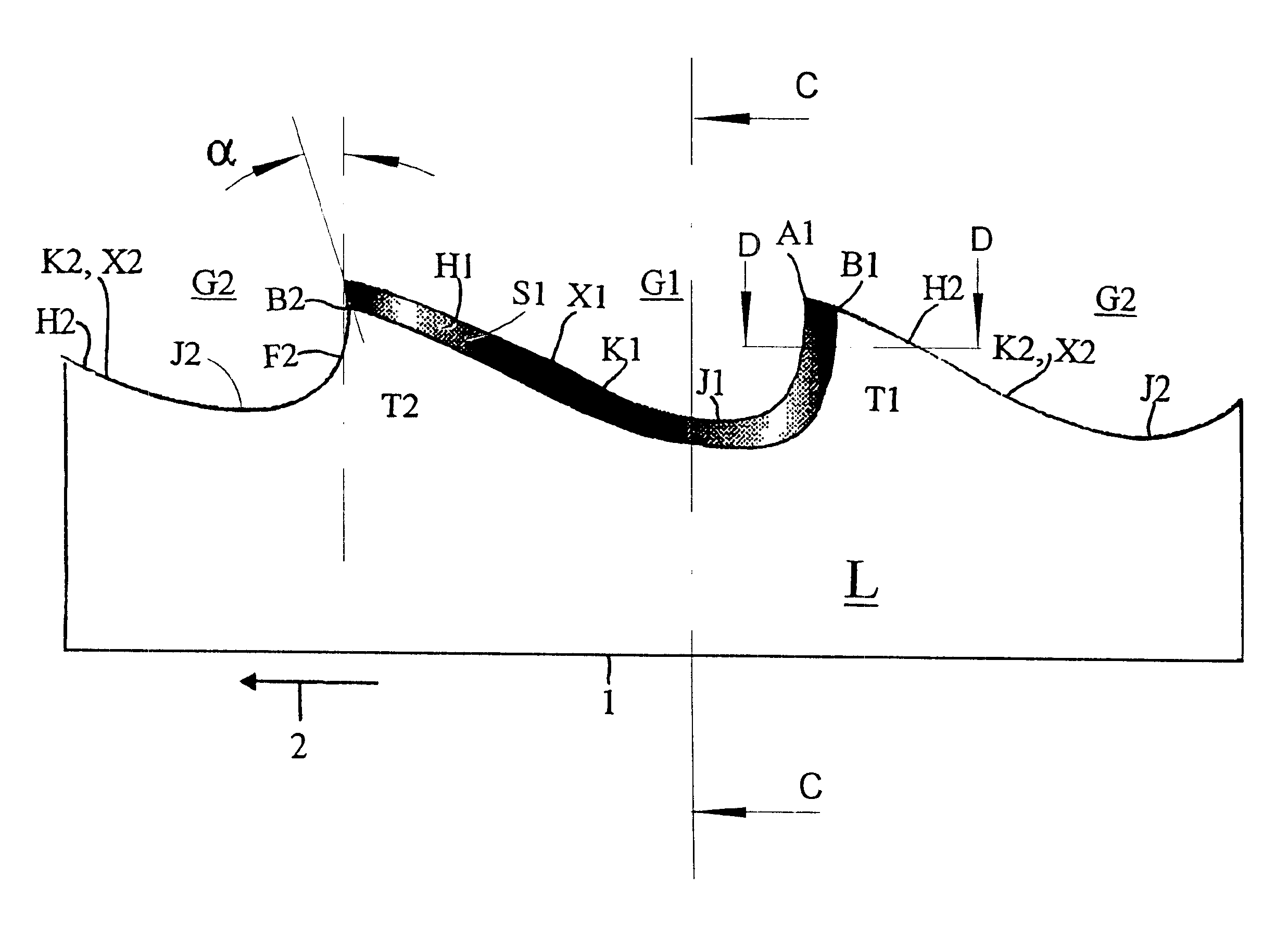
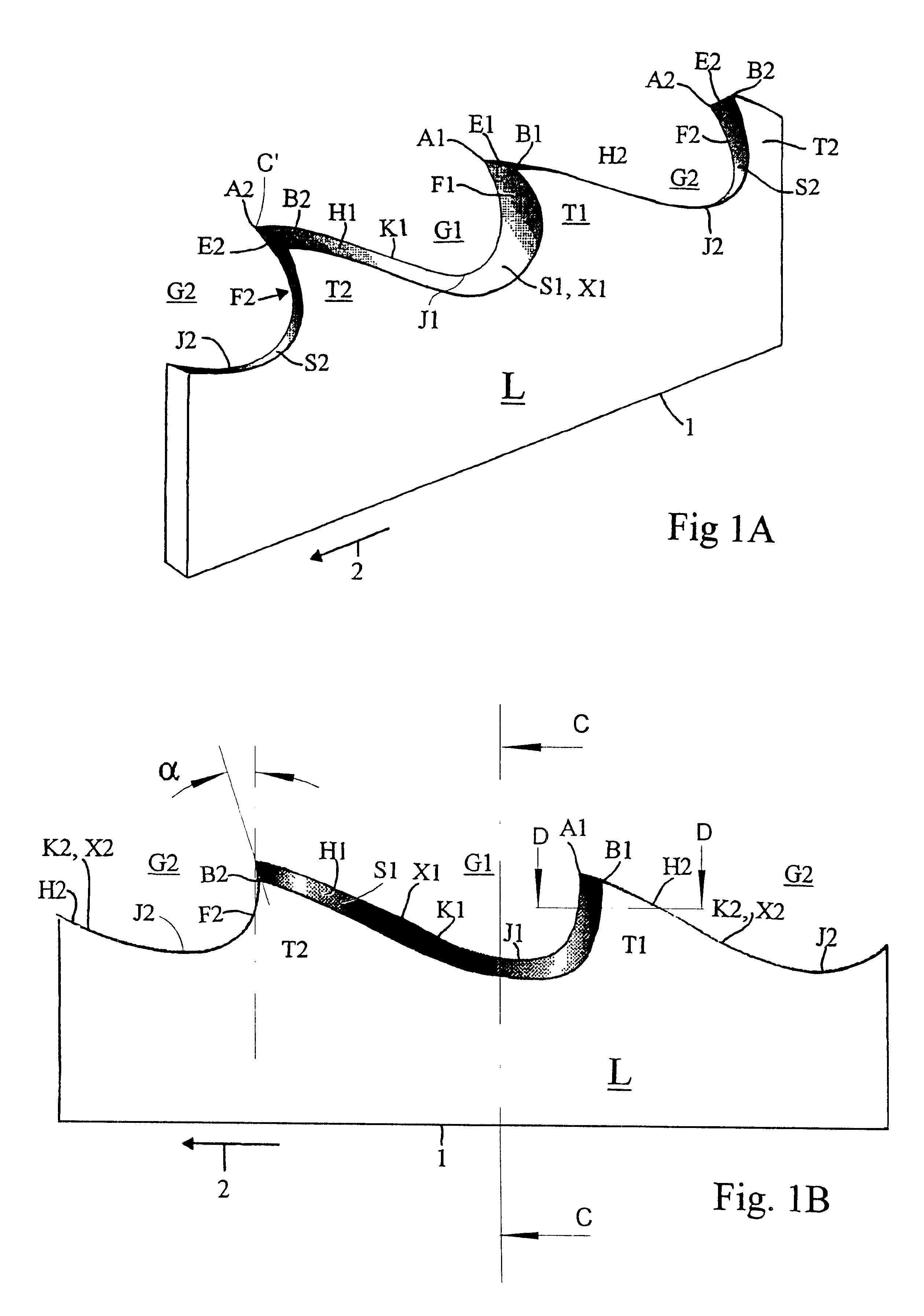
With reference first to FIGS. 1A and 1B, there is shown a section of a band saw blade 1 according to an embodiment which, when sawing in wood, plastics, fresh victuals and in comparatively soft metals, such as brass, has turned out to give very good results, as has been mentioned in the foregoing. The sawing direction is shown by an arrow 2. The blade thickness (gauge) is strongly exaggerated. A first tooth is designated T1 and second teeth on each side of the first tooth have been designated T2. The tooth edges at the tip of the tooth points of the teeth T1 and T2 have been designated E1 and E2, respectively. The tooth edge E1 on the first tooth T1 extends over the saw blade 1 between a right hand tooth corner A1 and a left hand tooth corner B1, while the tooth edges E2 extend between a right hand tooth corner A2 and a left hand tooth corner B2. The right planar side of the blade 1, which is hidden in FIGS. 1A and 1B, is denoted R, while the opposite, left hand planar side, turned ...


PUM

PropertyMeasurementUnit
angleaaaaaaaaaa
angleaaaaaaaaaa
angleaaaaaaaaaa

Abstract

A saw blade with teeth has a tooth point with a tooth edge (E1, E2). A tooth face is on the front side of the tooth and a tooth back is behind the tooth edge. A tooth gullet (G1, G2) is defined as the space between the tooth edges of two adjacent teeth. The tooth edge (E1, E2) extends between a right hand tooth corner (A1, A2) and a left-hand tooth corner (B1, B2). A first tooth gullet, disposed between the tooth edge (E1) of a first tooth (T1) and the tooth edge (E2) of the next tooth (T2) is beveled. A sloping surface (S1) extends from the first tooth edge (E1) in the rear end of the first tooth gullet downwardly along the tooth face and to at least the tooth bottom.

Description

The invention concerns a band saw blade with teeth having a tooth point with a tooth edge, a tooth face on the front side of the tooth as viewed in the direction of sawing, a tooth back behind the tooth edge, and a tooth bottom between the tooth face on each tooth and the tooth back on the next tooth in front of said each tooth, and tooth gullets, wherein a tooth gullet is defined as the space between the tooth edges of two adjacent teeth, said saw blade having two planar sides; a right hand side and a left hand side when the saw blade is viewed obliquely from above in the direction of sawing, wherein said tooth edge extends between a right hand tooth corner and a left hand tooth corner with reference to said viewing direction.Saw teeth of band saw blade work as tiny planing tools generating chips at high speed by planing and / or tearing, the chips being collected and removed in the tooth gullets. The development of increasingly efficient band saws has aimed at further developing thi...

Claims


Application Information

Patent Timeline
Patent Type & Authority Patents(United States)
IPC IPC(8): B23D61/12B23D61/00
CPCB23D61/121Y10T83/707Y10T83/9317Y10T83/9319Y10T83/9346Y10T83/9362
Inventor HAKANSSON, WILLIAMHAKANSSON, BENGT EMANUEL
Owner HAKANSSON WILLIAM
Why Eureka
Try Eureka