
Deployable roof mounted equipment rack for tall vehicles

a technology for vehicles and equipment, which is applied to vehicle components, other load-carrying vehicles, supplementary fittings, etc., can solve the problems of complicated access to the rear door or hatch, inability to pull a boat, trailer, etc., and inconvenient if not difficult access of a typical roof rack

Inactive Publication Date: 2004-01-27
BYRNES JAMES MICHAEL
View PDF18 Cites 43 Cited by
  • Summary
  • Abstract
  • Description
  • Claims
  • Application Information

AI Technical Summary

Benefits of technology

The solution provides enhanced accessibility, ease of use, and durability, allowing operation by average-height individuals without complex assembly or adjustments, while maintaining cargo accessibility and strength for off-road use, and is easily removable and collapsible for storage.

Problems solved by technology

Although these vehicles are commonly used for carrying bicycles, ski's, luggage, lumber, etc., their roof height creates inconvenient if not difficult access for a typical roof rack.
An issue with some of these design's however is that access to the rear door or hatch is complicated.
A limitation with all of these designs is the inability to also pull a boat, trailer, etc. while using the hitch rack.
Other lesser concerns with hitch racks are their impact on rear view visibility, and higher vulnerability to equipment damage in traffic and parking.
A hitch rack is also unable to carry certain types of equipment such as kayaks and shell-type equipment carriers, as well as lumber, plywood, and other large items better carried outside the vehicle.
U.S. Pat. No. 5,673,831 by Spratt (1997) effectively uses torsion springs to counterbalance the cargo load however the luggage rails of most vehicles may not accept the pull-out forces caused by reacting these torsion spring forces without augmenting their attachment to the vehicle.
Neither the Spratt, Hetu, or forms of most of the aforementioned patents latch automatically when placed into their stowed positions, making inadvertent deployment a higher risk.

Method used


Image

  • Deployable roof mounted equipment rack for tall vehicles
  • Deployable roof mounted equipment rack for tall vehicles
  • Deployable roof mounted equipment rack for tall vehicles

Examples


Embodiment Construction

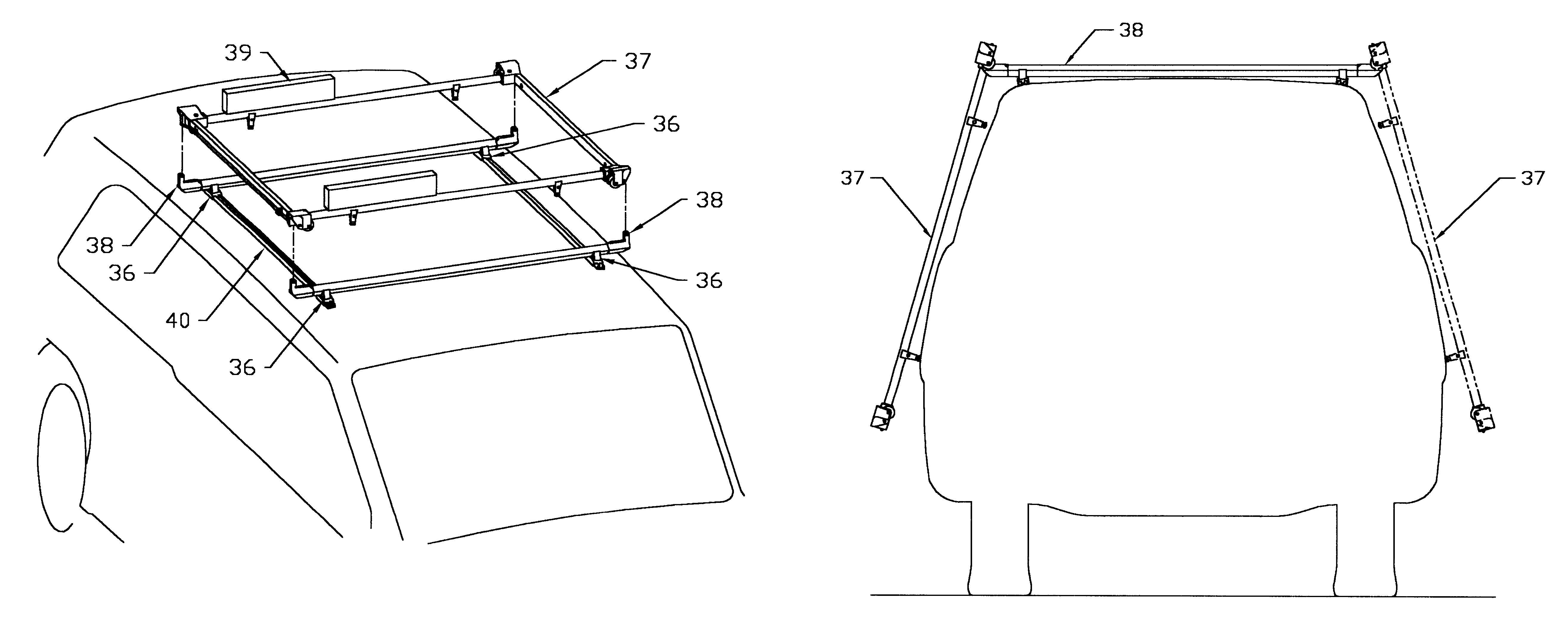
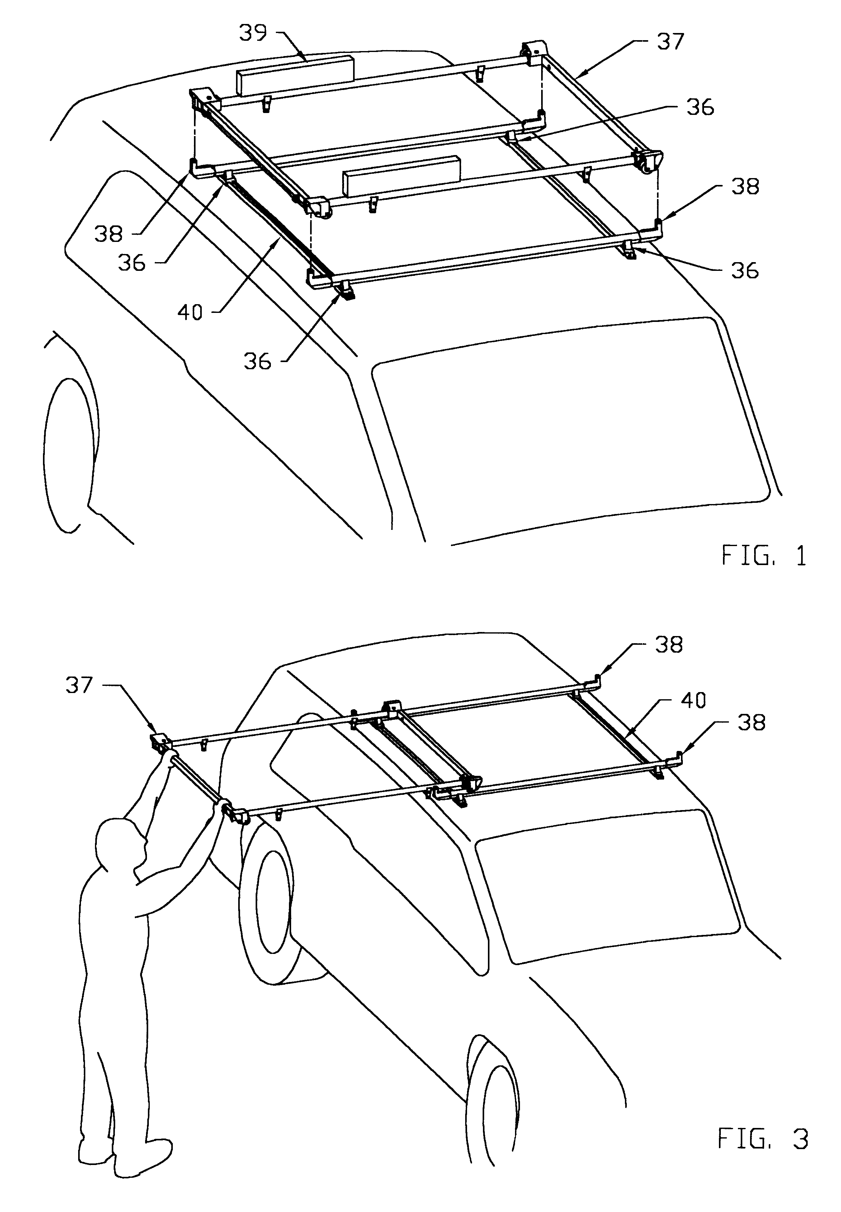
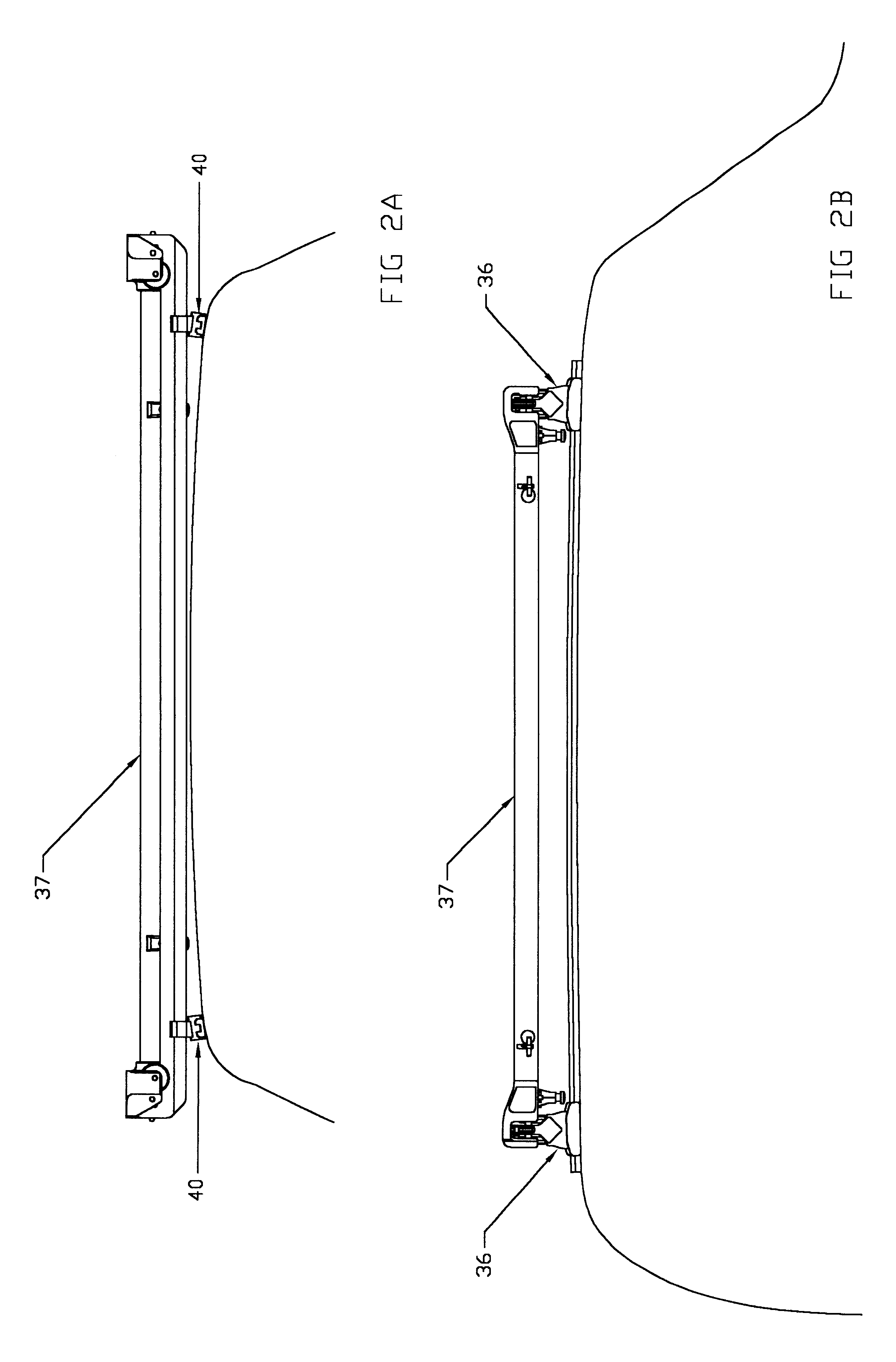
Shown in FIG. 1, the roof mounted equipment rack assembly is comprised of a carriage 37, two track members 38, and four roof mount adapter assemblies 36. The device does not include equipment mounts in the design as the carriage 37 is specifically configured to accept common aftermarket types of mounts. The ski mounts 39 in FIG. 1 are shown for reference only as a typical user-mounted arrangement. In general, the preferred embodiment keeps as much of the componentry as practical on the carriage 37. Alternatively, it would be possible to simplify the carriage 37 with only latch pins and rollers in each of its corners and place the active latching hardware onto the track members 38 (not shown). FIGS. 2a and 2b shows the symmetry of the design about the geometric center of the equipment rack assembly in each view. A symmetrical configuration allows the carriage to be deployed to either side of the vehicle and simplifies the overall hardware set FIG. 4B is the same view as FIG. 2A but w...


PUM


Abstract

A deployable roof mounted equipment rack apparatus especially suited for tall vehicles. The device contains a carriage that can be manually deployed from its horizontal position on the vehicle's roof to a near vertical position on either side of the vehicle using rollers guided by a fixed set of roof mounted tracks. The device is designed to accept commercially available equipment mounting hardware to allow attachment of various types of cargo. The carriage latches automatically when stowed on the rooftop tracks. The carriage can be removed from the vehicle once unlatched and readily collapsed to facilitate remote storage.

Description

This device relates to rooftop mounted equipment carriers for vehicles, specifically forms configured for improved accessibility.BACKROUND OF THE INVENTIONFor many years luggage racks on cars have been provided as a convenient way for hauling baggage and larger items better kept outside the vehicle such as sports equipment. Their design provides an accessible and sizeable platform when used on a typical sedan. However, more recently Sport Utility Vehicles (SUV's) and minivans have become increasingly popular. Although these vehicles are commonly used for carrying bicycles, ski's, luggage, lumber, etc., their roof height creates inconvenient if not difficult access for a typical roof rack. A 6-foot tall person may need to stand on a rear tire or door sill to gain full access to the roof of an SUV. One popular alternative to the roof rack has been the trailer-hitch mounted equipment rack. An issue with some of these design's however is that access to the rear door or hatch is complica...

Claims


Application Information

Patent Timeline
Patent Type & Authority Patents(United States)
IPC IPC(8): B60R9/042B60R9/00
CPCB60R9/042
Inventor BYRNES, JAMES MICHAEL
Owner BYRNES JAMES MICHAEL
Learn More