Check patentability & draft patents in minutes with Patsnap Eureka AI!

Electric positional actuator

a technology of electric position actuator and actuator, which is applied in the direction of motor/generator/converter stopper, dynamo-electric converter control, mechanical control devices, etc., can solve the problem of partly lost power increase of the cylinder

Inactive Publication Date: 2004-01-27
BORGWARNER INC
View PDF9 Cites 30 Cited by
  • Summary
  • Abstract
  • Description
  • Claims
  • Application Information

AI Technical Summary

Problems solved by technology

However, the power increase from the cylinders is partly lost due to the parasitic losses from driving the compressor by the engine.

Method used


Image

  • Electric positional actuator
  • Electric positional actuator
  • Electric positional actuator

Examples


Embodiment Construction

The following discussion of the embodiments of the invention directed to an electric positional actuator is merely exemplary in nature, and is in no way intended to limit the invention or it's applications or uses. Particularly, the actuator of the invention is described herein as being used to control air flow in a turbocharger or a supercharger. However, as will be appreciated by those skilled in the art, the actuator of the invention has application for actuating many other types of actuated devices.

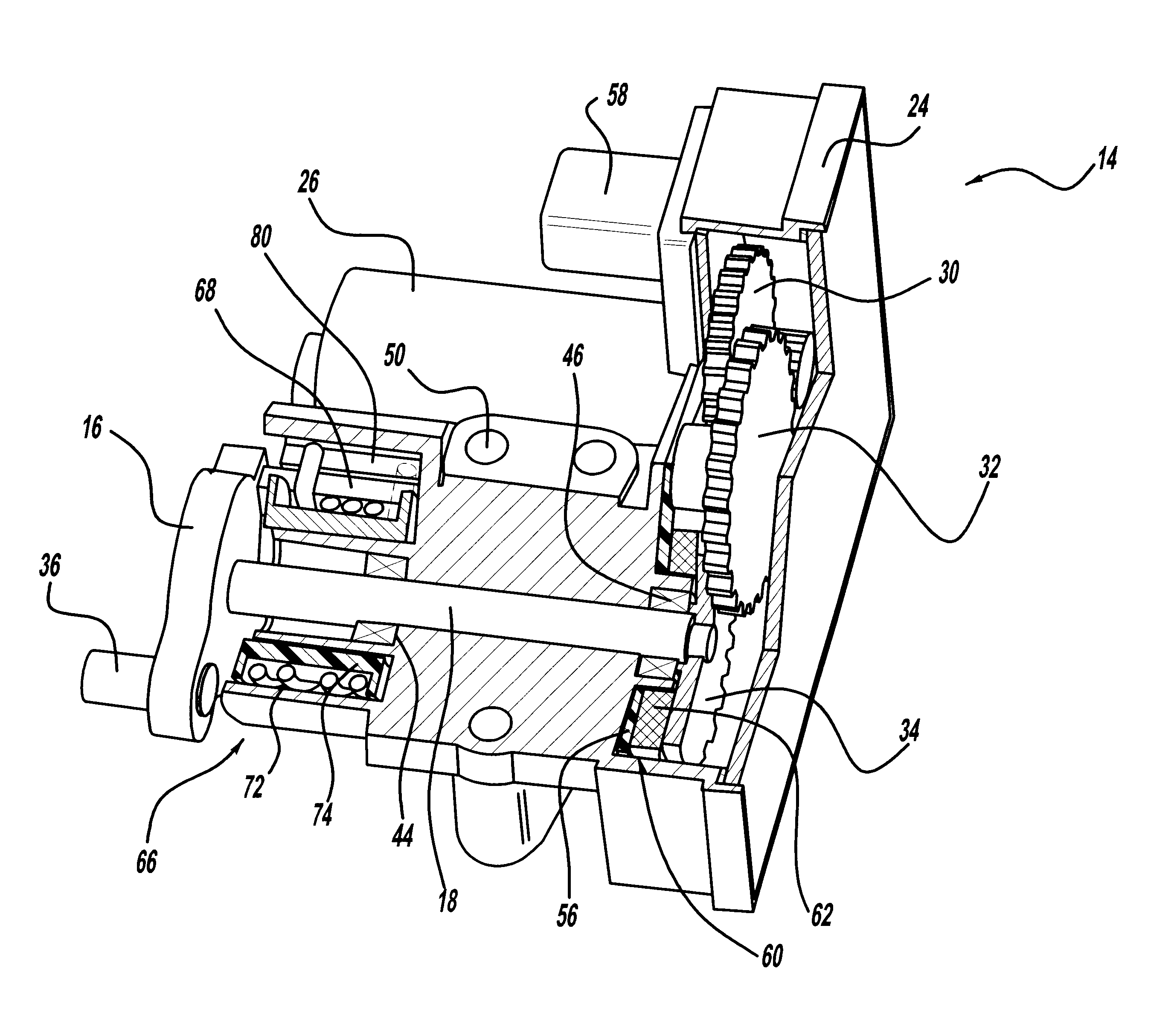
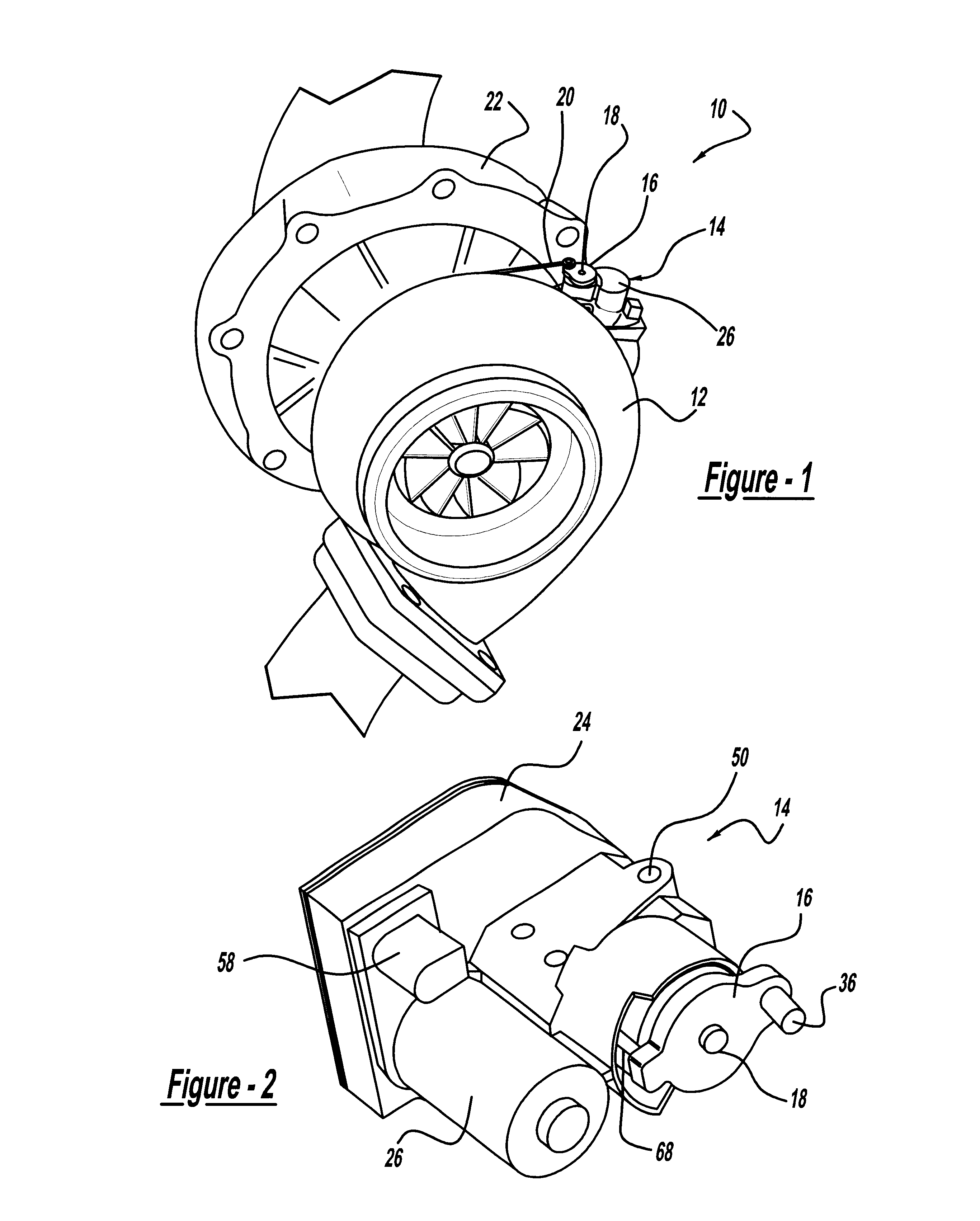
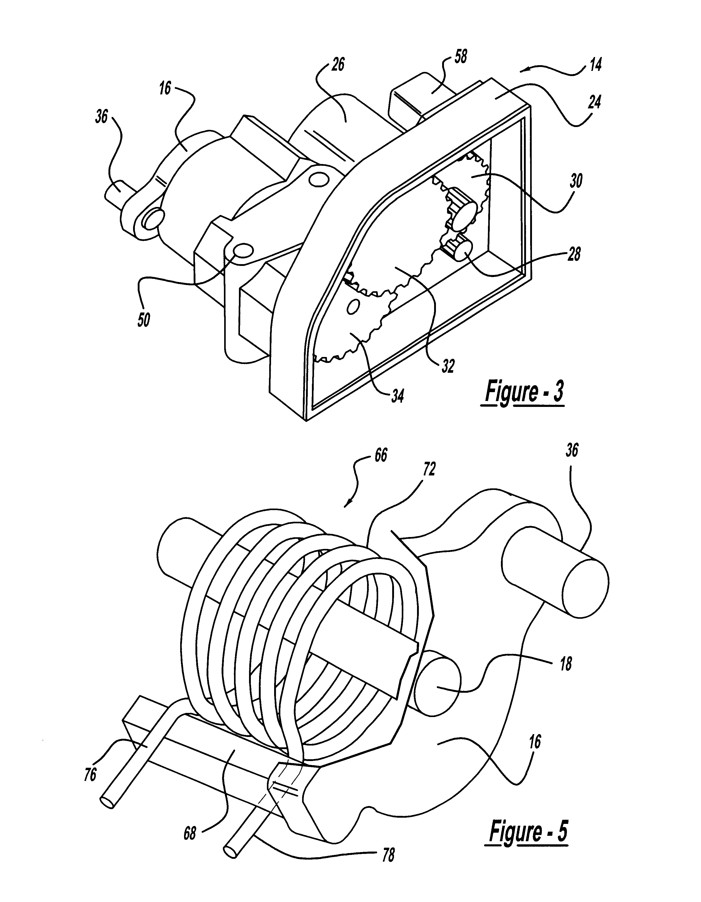
FIG. 1 is a perspective view of a turbocharger 10 including a turbine 12, a compressor 22 and an electric positional actuator 14, according to an embodiment of the present invention. The turbocharger 10 is intended to represent any turbocharger known in the art that includes a valve (not shown) for controlling the flow of air through the turbocharger 10. One end of a link-bar 16 is coupled to an output shaft 18 of the actuator 14 and the other end of the link-bar 16 is coupled to one ...


PUM


Abstract

An electric positional actuator that includes a default device for positioning the actuated device in a default position. The actuator includes an electric motor that controls the rotational position of a shaft through a gear system. When the shaft rotates, it moves a link-bar that actuates the actuated device. A rotational sensor coupled to a printed circuit board detects the position of the shaft, and provide a feedback signal of the shaft's position. The default device includes a spring wrapped around the shaft. When the link bar is rotated away from its default position, one leg of the spring remains in contact with a housing spring boss while the other leg of the spring is in contact with the link bar opposing the movement and trying to return the link-bar to the default position.

Description

1. Field of the InventionThis invention relates generally to an electric positional actuator and, more particularly, to an electric positional actuator employing a default positioning device for returning an actuated device to a desired default position in the event of actuator failure, where the actuator has particular application for controlling air flow through a turbocharger or a supercharger.2. Discussion of the Related ArtIn a four-stroke internal combustion engine, the combustion air and fuel mixture typically enters the cylinders of the engine under atmospheric pressure. By pressurizing the combustion air before it enters a cylinder, more fuel can be mixed with the high-pressure air to obtain the desired air / fuel mixture, and thus, more power can be delivered for each stroke of the cylinder. A supercharger employs a compressor driven by the engine to increase the combustion air pressure. However, the power increase from the cylinders is partly lost due to the parasitic losse...

Claims


Application Information

Patent Timeline
Patent Type & Authority Patents(United States)
IPC IPC(8): G05G5/00G05G5/05F02B37/22F02B37/12F02D9/02F02D11/10
CPCG05G5/05F02B37/12F02B37/22F02D11/107F02D2009/0269F02D2009/0277
Inventor PRINGLE, HALKEEFOVER, ROBERTHALSIG, MICHAELDUDDLES, JOHN
Owner BORGWARNER INC
Features
  • R&D
  • Intellectual Property
  • Life Sciences
  • Materials
  • Tech Scout
  • Unparalleled Data Quality
  • Higher Quality Content
  • 60% Fewer Hallucinations
Learn More