Direct-injection spark-ignition engine

a spark ignition and injection technology, applied in the direction of combustion engines, machines/engines, cylinders, etc., can solve the problems of increasing the amount of hydrocarbon emissions, affecting the combustion process,

Inactive Publication Date: 2004-02-03
MAZDA MOTOR CORP
View PDF11 Cites 11 Cited by
  • Summary
  • Abstract
  • Description
  • Claims
  • Application Information

AI Technical Summary

Benefits of technology

In this construction, the injector injects the fuel during a compression stroke in such a manner that a fuel spray and the tumble collide with each other in the cavity from approximately opposite directions during the stratified charge combustion operation. This serves to accelerate atomization of the fuel and produce the stratified combustible mixture around the spark plug located at the central part of the ceiling of the combustion chamber by stratifying a mixture of the fuel spray and air. The fuel spray is decelerated by its collision with the tumble, creating a situation in which the mixture floats beneath the central part of the ceiling of the combustion chamber. As a result, compared to the aforementioned prior art arrangement of Japanese Unexamined Patent Publication No. 2000-120440 in which the mixture is simply transported by the tumble, the period of time during which the combustible mixture stays around the spark plug is extended, resulting in an increase in the degree of freedom in determining fuel injection and ignition timing. The arrangement of this invention also serves to reduce adhesion of the fuel to the cavity surface and increase the effect of improving fuel economy by mixture strification.

Problems solved by technology

Thus, flame propagation tends to be hindered by the cavity surface during this stage.
Another problem of this approach is that the amount of hydrocarbon (HC) emissions could increase due to fuel adhesion to the cavity surface.
Furthermore, flame propagation tends to be hindered by the central ridge in the .omega.-shaped cavity during an early stage of combustion.
This construction also has a problem that the injected fuel tends to adhere to the surface of the arc-shaped recess close to the intake valve.

Method used


Image

  • Direct-injection spark-ignition engine
  • Direct-injection spark-ignition engine
  • Direct-injection spark-ignition engine

Examples


first embodiment

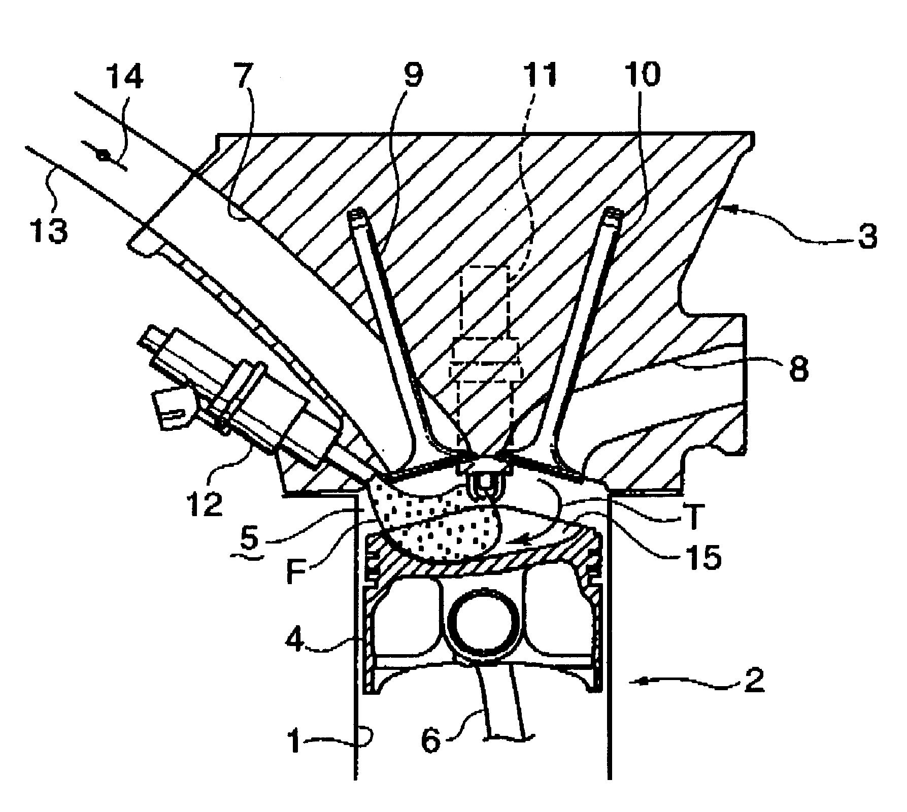
FIG. 1 is a cross-sectional view showing the construction of a principal portion of a direct-injection spark-ignition engine according to the invention. As shown in this Figure, the engine comprises a cylinder block 2 in which a plurality of cylinders 1 are arranged, a cylinder head 3 mounted on top of the cylinder block 2, and a plurality of pistons 4 which are fitted in the in a manner that the pistons 4 can move up and down in the respective cylinders 1. There is formed a combustion chamber 5 in each cylinder 1 just between the piston 4 and the cylinder head 3. Each piston 4 is linked to a crankshaft (not shown) located below the cylinder block 2 via a connecting rod 6.

As can be seen from the cross-sectional view of FIG. 1, a central part of the ceiling of the combustion chamber 5 in each cylinder 1 is higher than a peripheral part. In this embodiment, the ceiling of the combustion chamber 5 has a pent-roof structure having two-sides slopes (inner surfaces) extending obliquely do...

second embodiment

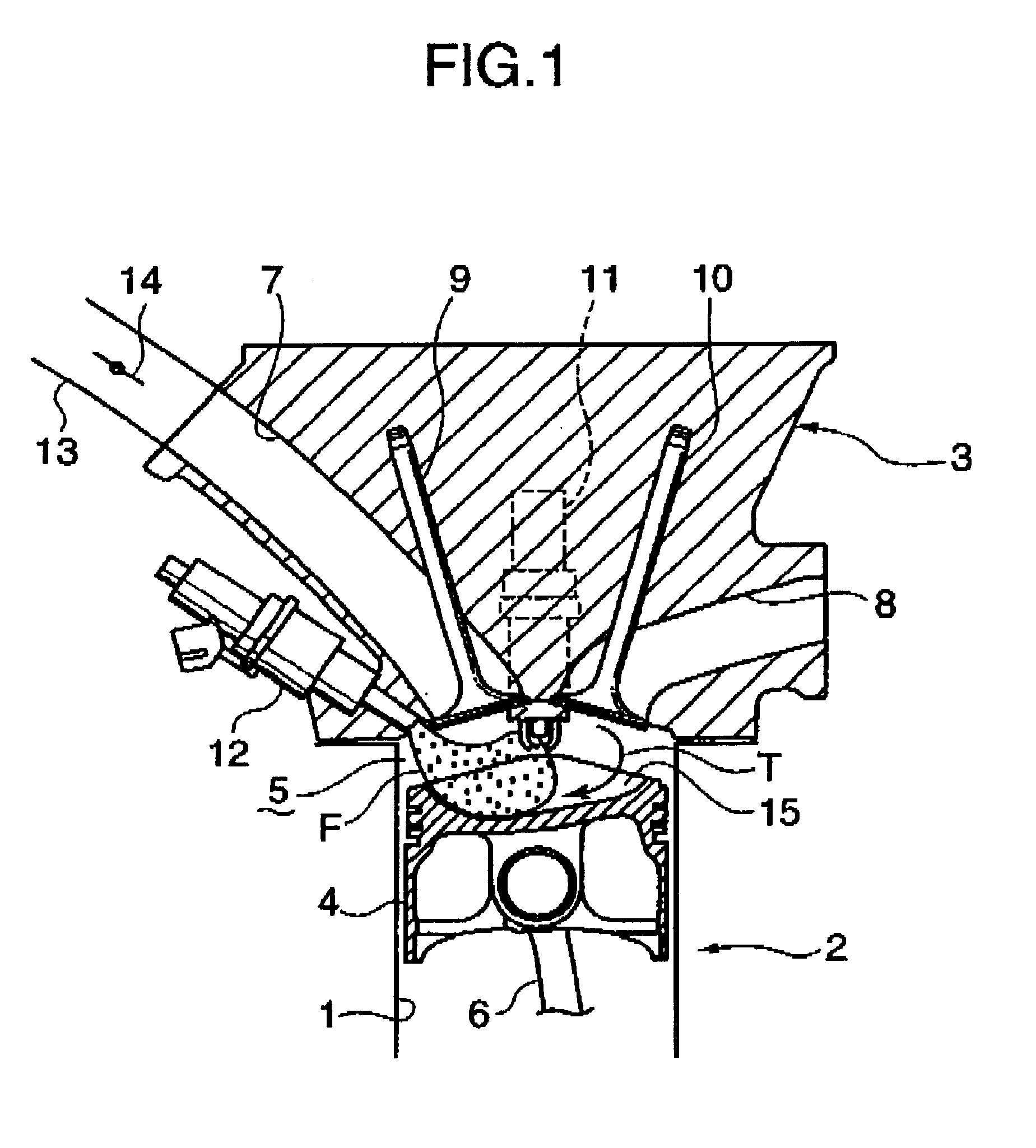
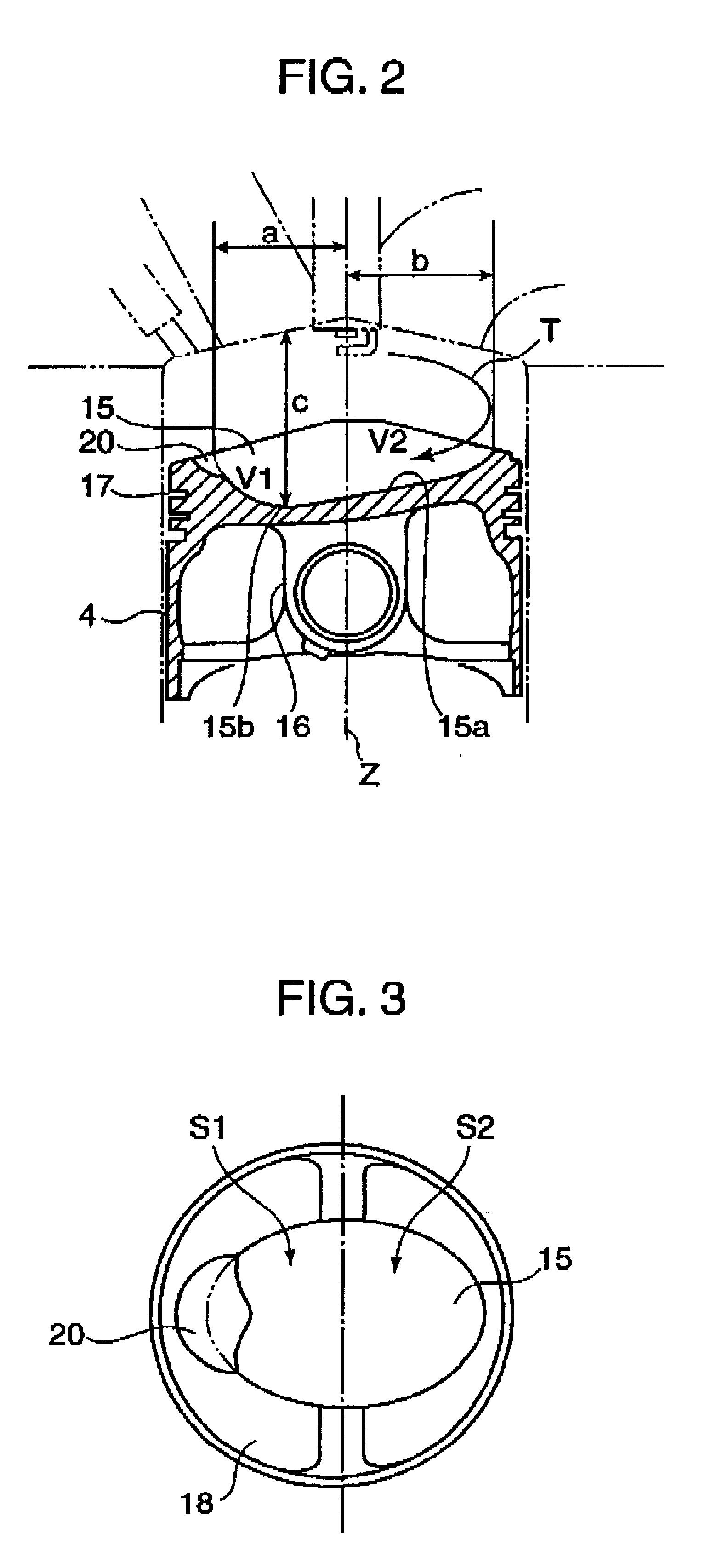
A piston of a direct-injection spark-ignition engine also has a cavity 15 formed in the piston head as illustrated. As viewed from a direction from which a tumble T seems to be turning clockwise, the bottom surface 15a of this cavity 15 is lowest at a point near the left end of the cavity 15 and from this lowest point 15b the bottom surface 15a slopes gradually upward toward the right end of the cavity 15, except that the bottom surface 15a abruptly rises in a steplike fashion at a specific position, where the aforementioned elevation step 20 is provided, midway along the sloping bottom surface 15a. A portion of the bottom surface 15a on the left side of the elevation step 20 is generally parallel to a portion of the bottom surface 15a on the right side of the elevation step 20, the right portion of the bottom surface 15a being higher than the left portion.

The engine of this embodiment has otherwise the same construction as the engine of the earlier-described first embodiment.

When ...


PUM


Abstract

A fuel spray and a tumble collide with each other from approximately opposite directions in a cavity formed in a piston head so that a combustible mixture stays around a spark plug for an extended period of time. An upper opening of the cavity is elongated to both the left and right sides of a cylinder axis. The distance between a ceiling of the combustion chamber and a bottom surface of the cavity is smaller on the right side of the cylinder axis than on the left side thereof and largest at least at a point where the cylinder axis crosses the bottom surface of the cavity, and a portion of the cavity to the left of the cylinder axis has a larger volumetric capacity than a portion of the cavity to the right of the cylinder axis, whereby a strong tumble is maintained up to a fuel injection point.

Description

BACKGROUND OF THE INVENTION AND RELATED ART STATEMENT1. Field of the InventionThe present invention relates to a direct-injection spark-ignition engine having an injector for injecting fuel directly into a combustion chamber. More particularly, the invention pertains to the construction of a direct-injection spark-ignition engine in which a stratified combustible mixture is produced around a spark plug using a tumble during operation by stratified charge combustion.2. Description of the Related ArtIn one example of a conventionally known direct-injection spark-ignition engine which is provided with an injector for injecting fuel directly into a combustion chamber, the air-fuel ratio is increased to produce a lean mixture and the injector injects the fuel during every compression stroke such that the mixture is locally distributed around a spark plug to cause stratified charge combustion in a low-speed low-load operating range, thereby achieving an improvement in fuel economy. For th...

Claims


Application Information

Patent Timeline
Patent Type & Authority Patents(United States)
IPC IPC(8): F02B31/00F02B23/10F02B31/08F02B17/00F02B75/00F02F1/24F02B75/12F02F3/26
CPCF02B17/005F02B23/104F02B31/085F02B2023/106F02B2075/125F02F2001/245Y02T10/125Y02T10/146Y02T10/123Y02T10/12
Inventor SAITO, FUMIHIKOOHTA, NORIYUKIYAMASHITA, HIROYUKIMARUBARA, MASASHISETO, MASATOSHIYOSHIDA, HIROYUKIYASUOKA, TAKEHIKOMATSUMOTO, MASAKAZU
Owner MAZDA MOTOR CORP
Why Eureka
Try Eureka