Method and system for noise notification

a technology of noise notification and system, applied in the field of system and method for noise notification, can solve the problems of not direct notification to the person responsible for noise, too noisy, and many noises created in the system

Inactive Publication Date: 2004-02-03
IBM CORP
View PDF11 Cites 33 Cited by
  • Summary
  • Abstract
  • Description
  • Claims
  • Application Information

AI Technical Summary

Problems solved by technology

A frequent complaint by office workers about their work environment is that it is too noisy.
Much of the noise is created by the workers themselves in the course of their work.
However, the noise is not always intentional, nor are they necessarily aware that they are speaking too loudly or making noise in any other way.
However, none of these systems directs notification to the person responsible for the noise.

Method used


Image

  • Method and system for noise notification
  • Method and system for noise notification
  • Method and system for noise notification

Examples


embodiment

Preferred Embodiment

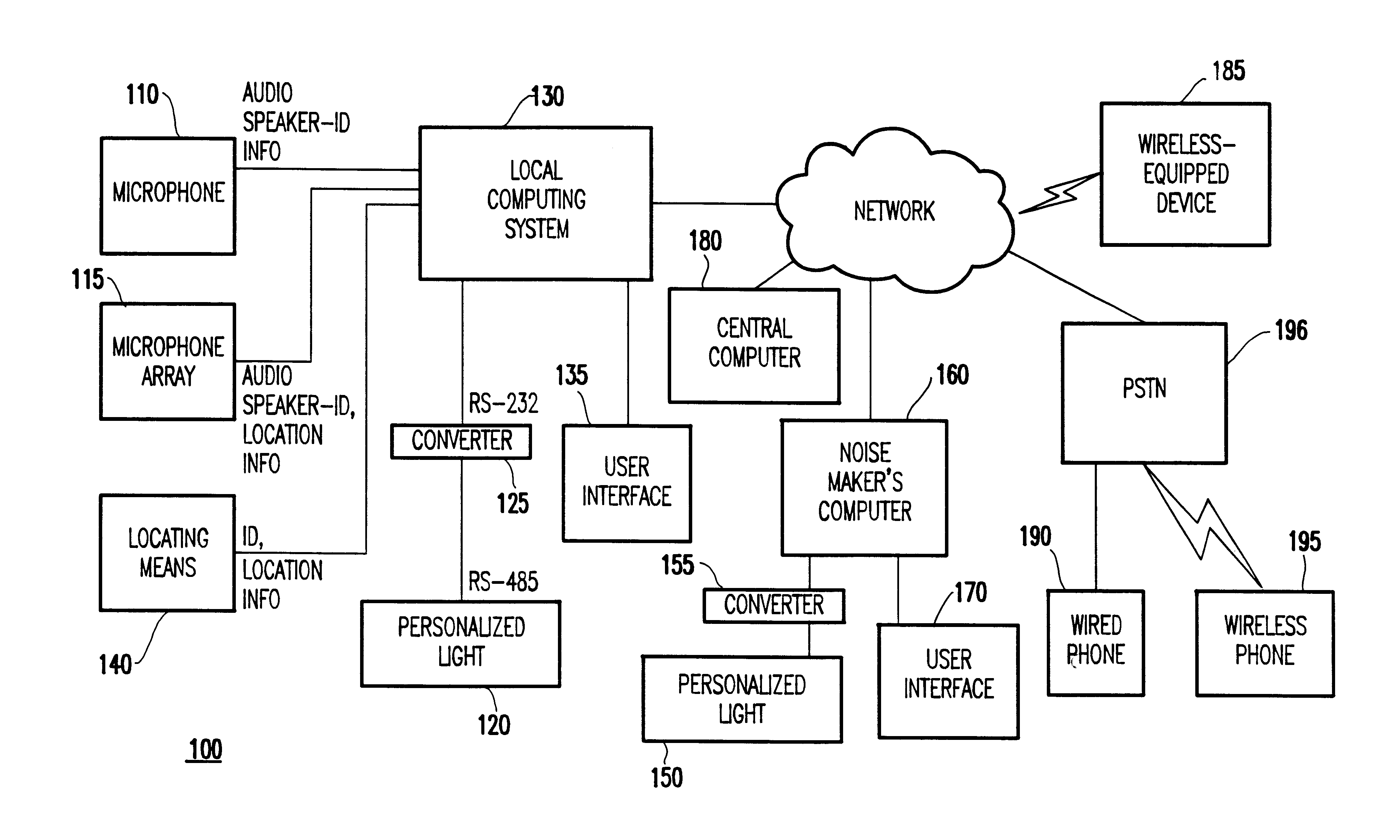
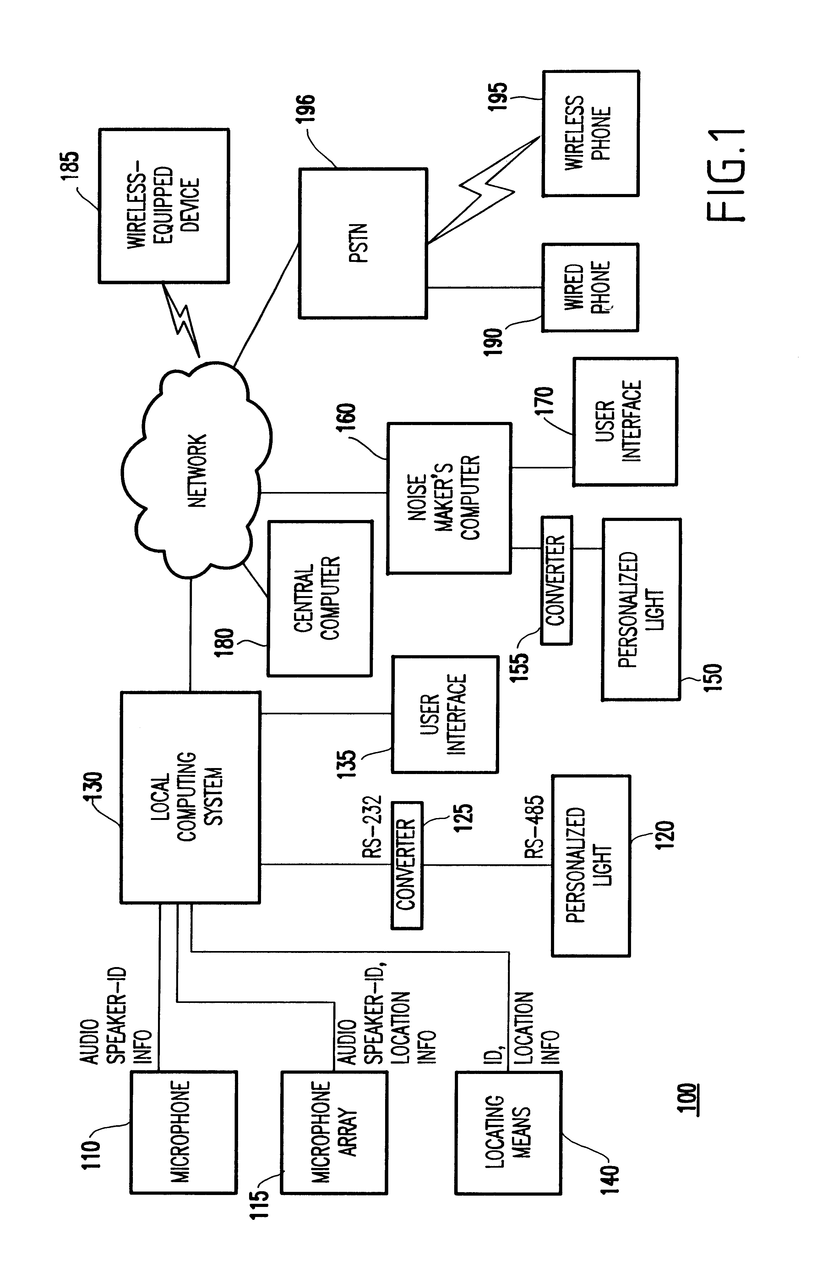
Turning to FIG. 1, a system 100 is shown for noise notification. Generally, sound (noise) is recorded using a microphone 110 or the like as an input device, and is digitized (e.g., at some predetermined sampling rate and encoding scheme). It is noted that the location and the approximate range of the microphone are known in advance. Thus, the approximate location of the source of the sound (e.g., the noise maker) can be detected based on the known location of the microphone. Further, the identification of the noise maker can be detected since the microphone can be made personal to a user (e.g., placed on the desk of the user).

Thereafter, samples are processed to measure loudness (e.g., each sample is squared, then summed and finally normalized by the number of summed samples. Samples may be taken over a given interval of time). This yields a number that indicates the average loudness (L) for that interval of time. A plurality of parameters are used as thresholds ...


PUM


Abstract

A system (and method) includes a sound monitoring system, a detector for identifying a source of the sound, a computing system for processing the sound to trigger a notification event, and a user interface system for notifying at least one individual responsible for the sound.

Description

1. Field of the InventionThe present invention generally relates to a system and method for noise notification, and more particularly to a system and method for identification of noise sources and subsequent notification to the noise sources.2. Description of the Related ArtA frequent complaint by office workers about their work environment is that it is too noisy. Much of the noise is created by the workers themselves in the course of their work. However, the noise is not always intentional, nor are they necessarily aware that they are speaking too loudly or making noise in any other way. Noise indicating light systems are known. However, none of these systems directs notification to the person responsible for the noise.Thus, a method must be found to identify individuals as noise sources and to notify them (or a person responsible for them such as a manager or the like) that they are creating too much noise. Hitherto, the present invention such a method and system have been unknow...

Claims


Application Information

Patent Timeline
Patent Type & Authority Patents(United States)
IPC IPC(8): G08B13/16G08B23/00
CPCG08B23/00G08B13/1672
Inventor CHOU, PAUL BAO-LUOGRUTESER, MARCO O.LAI, JENNIFER C.LEVAS, ANTHONYMOSKOWITZ, PAUL ANDREWWONG, DANNY CHAN YONG
Owner IBM CORP
Why Eureka
Try Eureka