
Polarization splitting backlight module

a backlight module and splitter technology, applied in the field of backlight modules, can solve problems such as limiting the quality of image display, and achieve the effect of reducing manufacturing costs and reducing optical loss in light beam outpu

Inactive Publication Date: 2004-02-10
S LIGHT OPTPELECTRONICS
View PDF3 Cites 13 Cited by
  • Summary
  • Abstract
  • Description
  • Claims
  • Application Information

AI Technical Summary

Benefits of technology

is to provide a polarization splitting backlight module for generating a light source of a single polarization state, which reduces the optical loss in light beam output, is suitable for mass production, and decreases manufacturing costs.
Another object of the present invention is to provide a polarization splitting backlight module, which is easily integrated with conventional light guides and achieves high-quality polarization splitting.
In order to enhance the optical performance, the ridge pitch of ridged surface of the under plate may be constant or not so as to increase the design freedom. Moreover, in order to increase the efficiency for altering the polarization states, the phase retardation reflection film is utilized. In addition, four lateral sides of the polarization splitting backlight module may be optionally coated with a reflection film, so as to increase the transmission efficiency of the light beams.
Furthermore, the polarization splitting backlight module according to the present invention can be easily integrated with a conventional liquid crystal display backlight module. This is achieved by attaching the polarization splitting film and the upper surface of the under plate according to the present invention to the upper side and lower side of the diffusion plate of the conventional backlight module respectively.
FIG. 8 shows the reflectivity of P-S polarized components over different wavelengths of light beams incident to a typical phase retardation reflection film of high reflectivity;

Problems solved by technology

Since the optical energy loss between the resultant and original light beams is considerable, the power consumption of a system using such a construction is very significant, thereby limiting the quality of the image display.

Method used


Image

  • Polarization splitting backlight module
  • Polarization splitting backlight module
  • Polarization splitting backlight module

Examples


Embodiment Construction

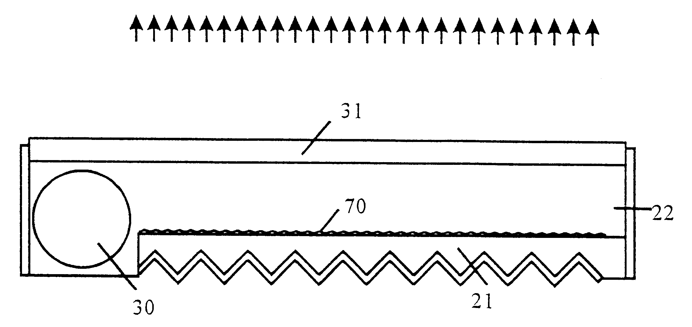
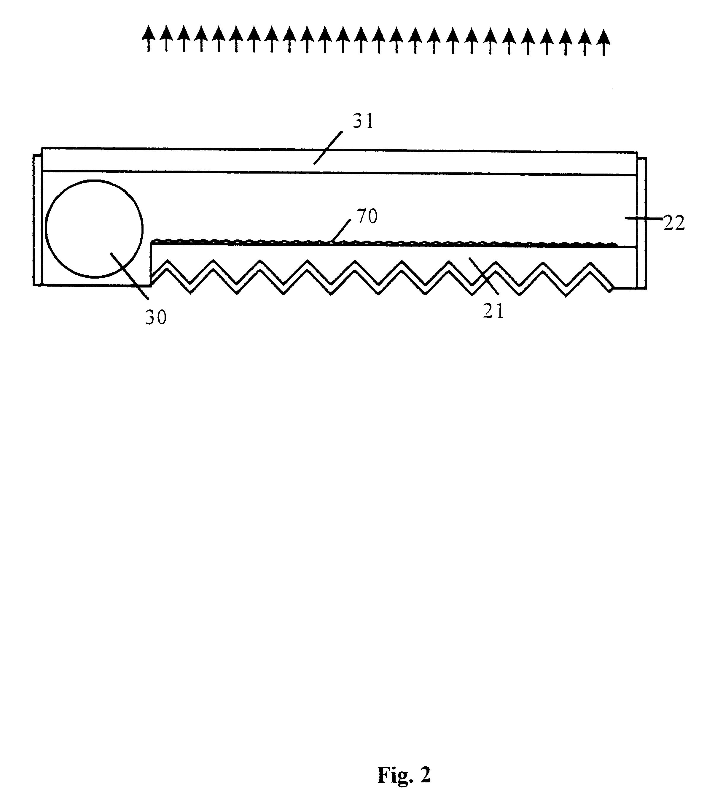
FIG. 2 illustrates the preferred embodiment of the polarization splitting backlight module according to the present invention. The polarization splitting backlight module is a laminated construction composed of an under plate 21, a light source 30, a substrate 22 and a polarization splitting film 31. A scattering structure 70 is provided between the under plate 21 and the substrate 22. The under plate 21 has a ridged lower surface and a phase retardation reflection film (not shown) coated thereon. The phase retardation reflection film functions to convert the light beams incident thereto in terms of polarization and then reflect the converted light beams. The scattering structure 70 also functions to convert the light beams in terms of polarization. Therefore, the efficiency of the light beams passing through the polarization splitting film 31 can be increased. In this embodiment, the ridge angle between any two neighboring ridges on the lower surface of the under plate 21 is 90 deg...


PUM

PropertyMeasurementUnit
ridge angleaaaaaaaaaa

Abstract

A polarization splitting backlight module for efficiently converting a non-polarized light beam emitted from the light source into a single polarization state is disclosed. The polarization splitting backlight module of the present invention comprises an under plate with a ridged lower surface, a light source, a special reflection film, a scattering structure, a substrate and a polarization splitting film. The light beam emitted from the light source is introduced into the scattering structure between the under plate and the substrate. After a series of processes, such as scattering, reflection, phase retardation and polarization beam-splitting, the light beam will pass through the polarization splitting film being of a single polarization state such that it could be utilized by electro-optical systems, such as liquid crystal displays. The present invention converts light beams into a single polarization state, and the efficiency thus is higher than that of a conventional backlight module. The present invention achieves brightness levels that are almost twice that of conventional backlight module.

Description

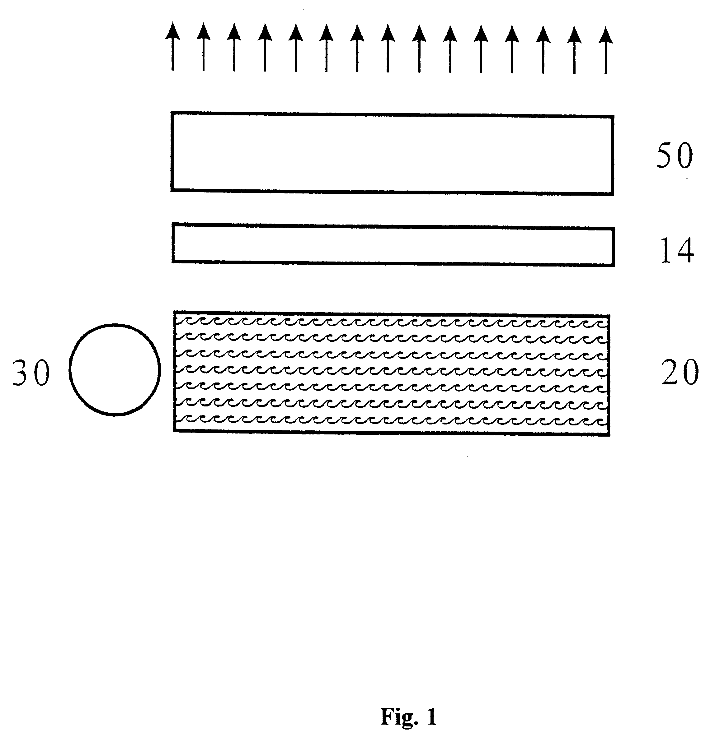
1. Field of the InventionThe present invention relates generally to backlight modules, and more particularly to a polarization splitter backlight module for converting a non-polarized light beam into a single polarization state.2. Description of the Related ArtWith the advent of the information technology (IT) age, there is an increasing demand for high-quality electro-optical displays (LCDs). Higher quality imaging requires the more efficient utilization of light sources. Conventionally, for obtaining single-polarized light beam output form a LCD backlight plate, a polarization plate is arranged near the light source to inhibit the passage of certain polarized light beams, whereby the polarized light beams which are not parallel are prevented form being transmitted. In practice, the resultant light beams of a single polarization state are less than half of those of the original light source in terms of illuminance.With reference to FIG. 1, a conventional liquid crystal display comp...

Claims


Application Information

Patent Timeline
Patent Type & Authority Patents(United States)
IPC IPC(8): F21V8/00G02B27/28G02B5/30G02F1/13G02F1/1335G02F1/13357
CPCG02B5/305G02B6/0038G02B6/0051G02B6/0056G02B27/283G02F1/13362G02F1/133615
Inventor LEE, CHIH-KUNGWU, JIUN-YANLEE, SHU-SHENGTANG, CHING-HENG
Owner S LIGHT OPTPELECTRONICS
Learn More