
Non-fixing type image forming method and non-fixing type image forming apparatus

a technology of image forming and non-fixing, which is applied in the direction of nanotechnology, thin material processing, instruments, etc., can solve the problems of increasing the amount of exhaust carbon dioxide generated by production, the difficulty of separating the toner fixed onto the image receiving sheet from the image receiving sheet, and the increase in the energy required for producing it, so as to reduce the amount of electric charge of the toner t on the image receiving sheet s, the effect of reducing the surface potential

Inactive Publication Date: 2004-03-02
MINOLTA CO LTD
View PDF15 Cites 2 Cited by
  • Summary
  • Abstract
  • Description
  • Claims
  • Application Information

AI Technical Summary

Benefits of technology

The present invention is made in view of these circumstances, and the object is to provide improved image forming method and image forming apparatus. More specifically, the object is to provide improved non-fixing type image forming method and image forming apparatus.
In addition, the electrostatic toner T can be fixed, but hot-melt toner which can be thermally fixed, for example, is not necessarily used. Therefore, a hard material can be used as the toner material, and thus long-life toner with less deformation, abrasion, fusion and the like can be adopted.

Problems solved by technology

It is difficult to separate the toner fixed onto the image receiving sheet from the image receiving sheet and to reuse the toner and the image receiving sheet.
However, as the present public is computerized, a lot of the toner and the image receiving sheets are consumed, so that the energy required for producing them and an amount of exhaust carbon dioxide generated by the production are increasing.
As a method of separating toner from an image receiving sheet in order to reuse an image receiving sheet on which a toner image is fixed, a deinking method utilizing an aqueous solution such as a surface-active agent is also known, but a lot of energy is required to remove moisture impregnating with an image receiving sheet such as paper, and removed toner cannot be reused because it is vitrificated.

Method used


Image

  • Non-fixing type image forming method and non-fixing type image forming apparatus
  • Non-fixing type image forming method and non-fixing type image forming apparatus
  • Non-fixing type image forming method and non-fixing type image forming apparatus

Examples


Embodiment Construction

of Peeling Characteristics of Toner from Image

As for the image receiving sheet on which the toner image is formed by the image forming method an the image forming apparatus of the present invention, a relationship between peeling of toner from the toner image (toner separated amount) and a surface potential (V) of the image receiving sheet observed when an amount of ions to be strewed was changed was studied. This will be explained below.

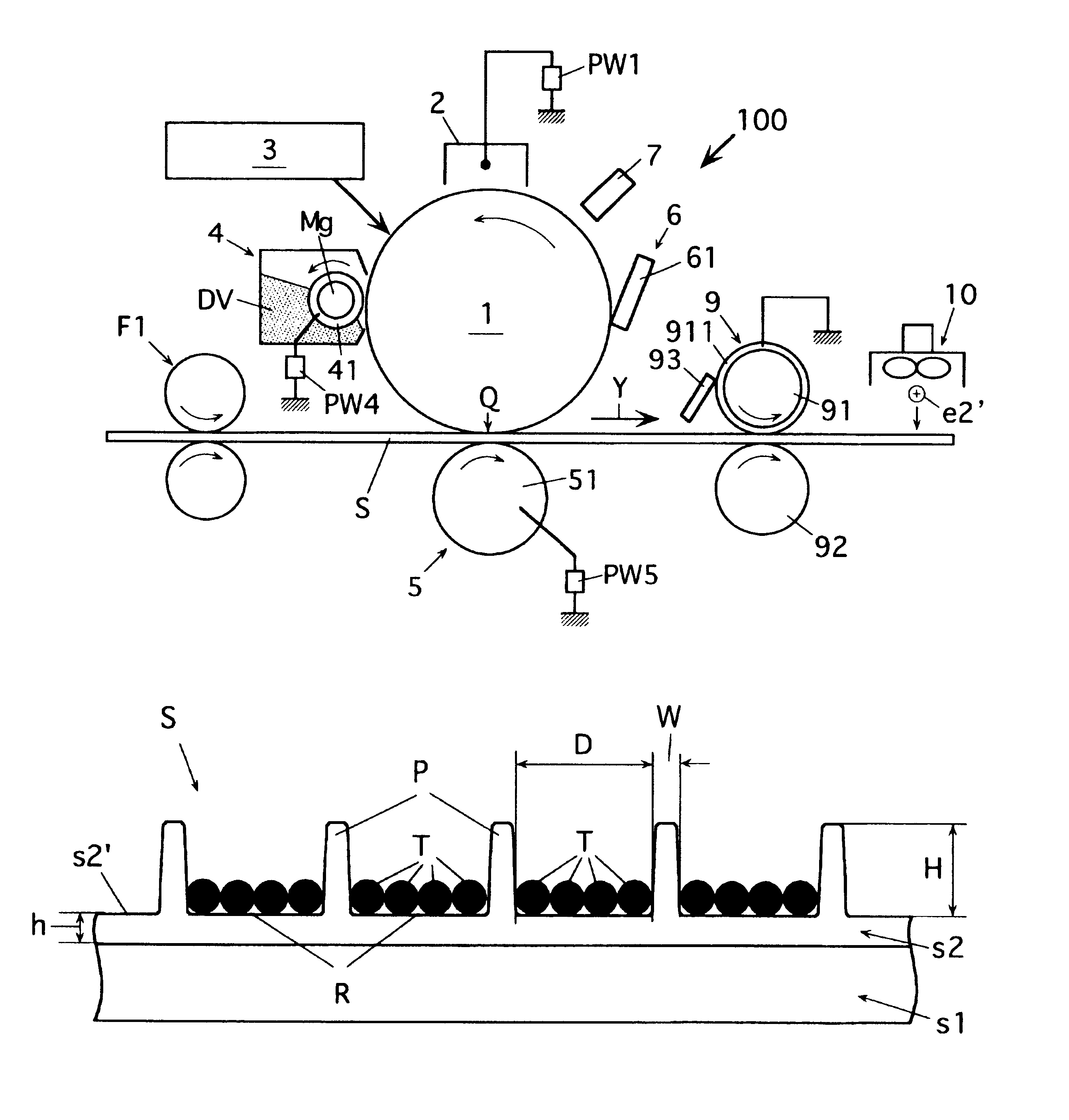
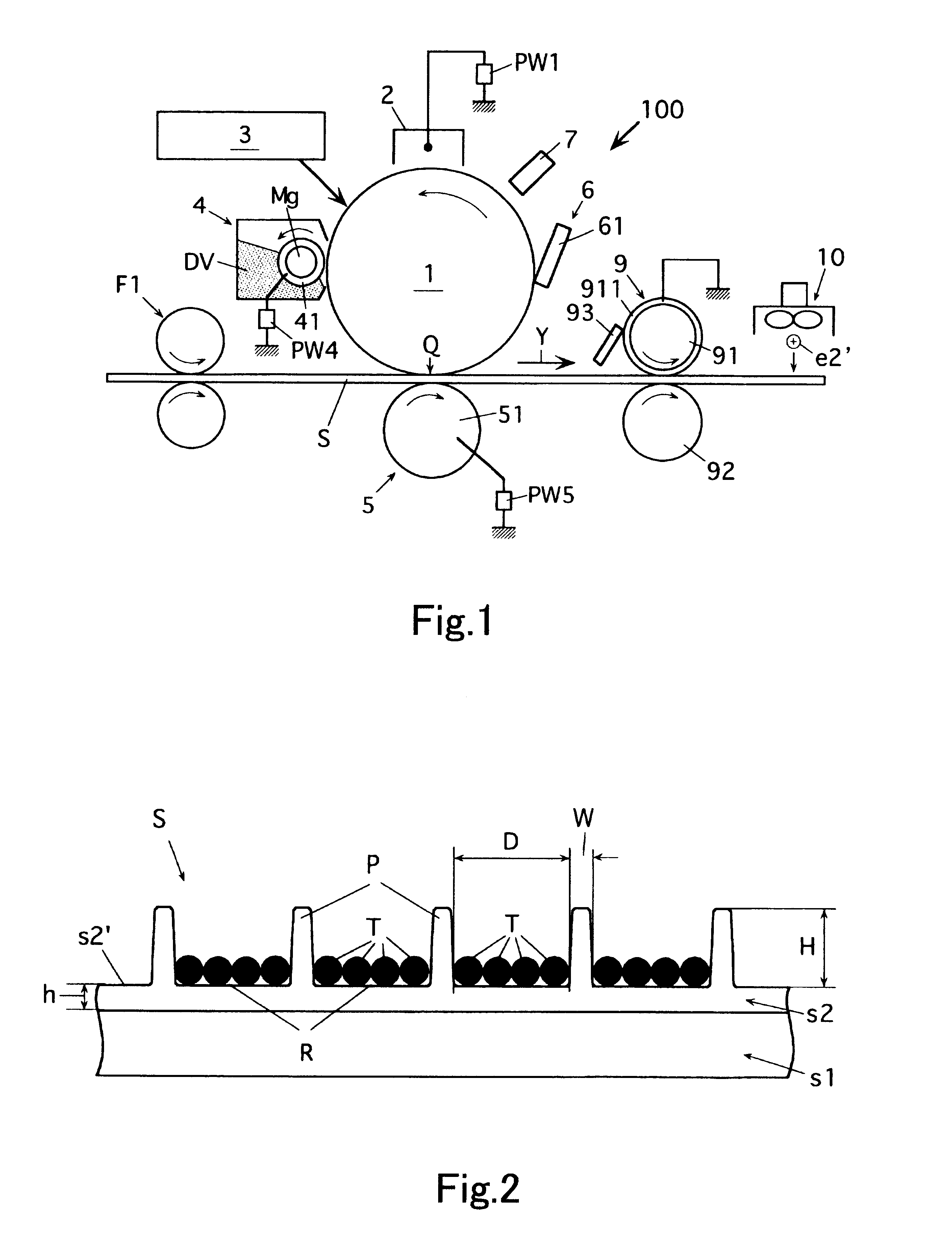
The experiment was carried out by using the image forming apparatus show in FIG. 1 in the following manner.

After the toner image was formed, an ion blow was given to the image formed surface of the image receiving sheet of which protrusions were cleaned, and the surface potential of the image receiving sheet was measured. At this time, the output of the ion blow was changed variously so that the surface potential of the image receiving sheet was changed.

After the toner image was formed in such a manner, an insulating film for measuring a toner separ...


PUM


Abstract

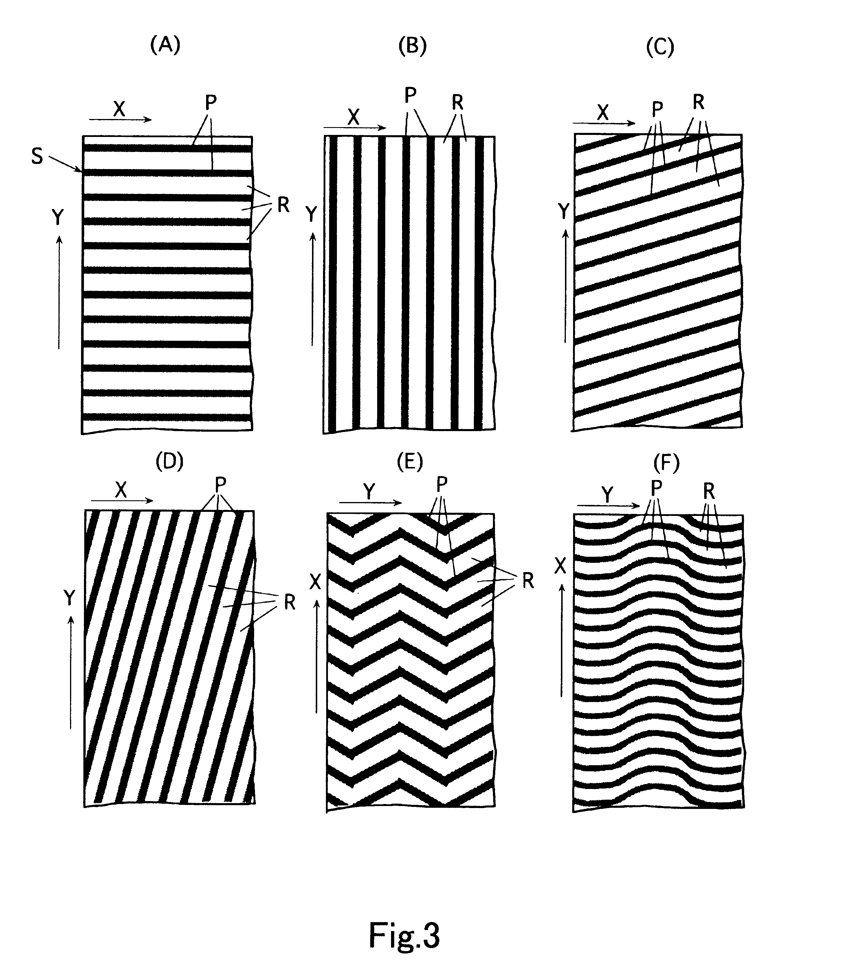
In the non-fixing type image forming method and apparatus which allow chargeable toner T to removably adhere to recessed portions R of an image receiving sheet S having an uneven surface s2' formed with a lot of the recessed portions R capable of housing the chargeable toner by an electrostatic force to form a toner image and allows protrusions P of the uneven surface s2' to protect the toner T adhering to the recessed portions R, after the toner image is formed on the image receiving sheet S, an amount of electric charges of the toner T on the image receiving sheet is reduced.

Description

This application is based on application No. JP 2001-169715 filed in Japan, the contents of which is hereby incorporated by reference.1. Field of the InventionThe present invention relates to an image forming method and an image forming apparatus which are improved. More concretely, the present invention relates to a non-fixing type image forming method of forming a toner image on a image receiving sheet and a non-fixing type image forming apparatus to be used for carrying out the image forming method.2. Description of the Related ArtAn image forming method of forming a toner image on an image receiving sheet has been carried out for a long time. The typical method is an electrophotographic image forming method.In the electrophotographic image formation, an electrostatic latent image carrier such as a photoreceptor is electrified so as to have a predetermined electric potential, and an image is exposed on the charging area according to document image information so that an electrost...

Claims


Application Information

Patent Timeline
IPC IPC(8): G03G15/00G03G15/22G03G21/00B65H5/00G03G7/00
CPCB82Y15/00G03G15/221G03G15/6588G03G21/00
Inventor MIZUNO, HIROSHIIZUTANI, AKIRA
Owner MINOLTA CO LTD
Learn More