Eureka AIR delivers breakthrough ideas for toughest innovation challenges, trusted by R&D personnel around the world.

Machine leveler

Inactive Publication Date: 2004-03-09
SCHRIEVER FREDERICK G
View PDF13 Cites 25 Cited by
  • Summary
  • Abstract
  • Description
  • Claims
  • Application Information

AI Technical Summary

Benefits of technology

I have overcome the forgoing problems of the prior art and at the same time reduced the cost of the leveler. This is accomplished by making the base of the leveler of a flat steel plate, which may be of any size desired by the customer. The upper face of this plate provides a wedge supporting surface. A hollow cover, which may be cast iron, is placed with its open face against the upper face of the base plate and screw fasteners extend through the cover and are threaded into the plate to secure the two parts together. A wedge is disposed inside the cover and rests on the upper face of the base plate. A wedge follower projects through the top of the cover, being guided therein for vertical movement, and having at its upper end an upwardly facing spherically curved load carrying surface, and at its lower end an inclined surface slidably bearing against the wedge. A wedge shifter in the form of a threaded adjusting screw extends through an end of the cover and engages the wedge to shift it to cause a rise or fall of the wedge follower. A wedge position indicator fastened to the wedge projects through the cover to indicate the position of the wedge therein. Finally, the upper surface of the cover is shaped to cause water or the like falling on the leveler to run off without entering the interior.

Problems solved by technology

Also, the design of the prior art levelers was such that if a customer wanted other than a standard size base, it was difficult to provide another size base without a substantially greater price.
A serious problem has been that in adjusting the levelers to level the load, the workmen may over-torque the adjusting screws causing them to break or strip the threads or causing the leveling wedge to break.
When such occurs the load, such as a machine tool or other heavy object, must be removed, then the leveler removed and either repaired or replaced, and the load again placed thereon, and the leveling procedure re-commenced, all of which substantially increases the cost of the installation.

Method used


Image

  • Machine leveler
  • Machine leveler
  • Machine leveler

Examples


Embodiment Construction

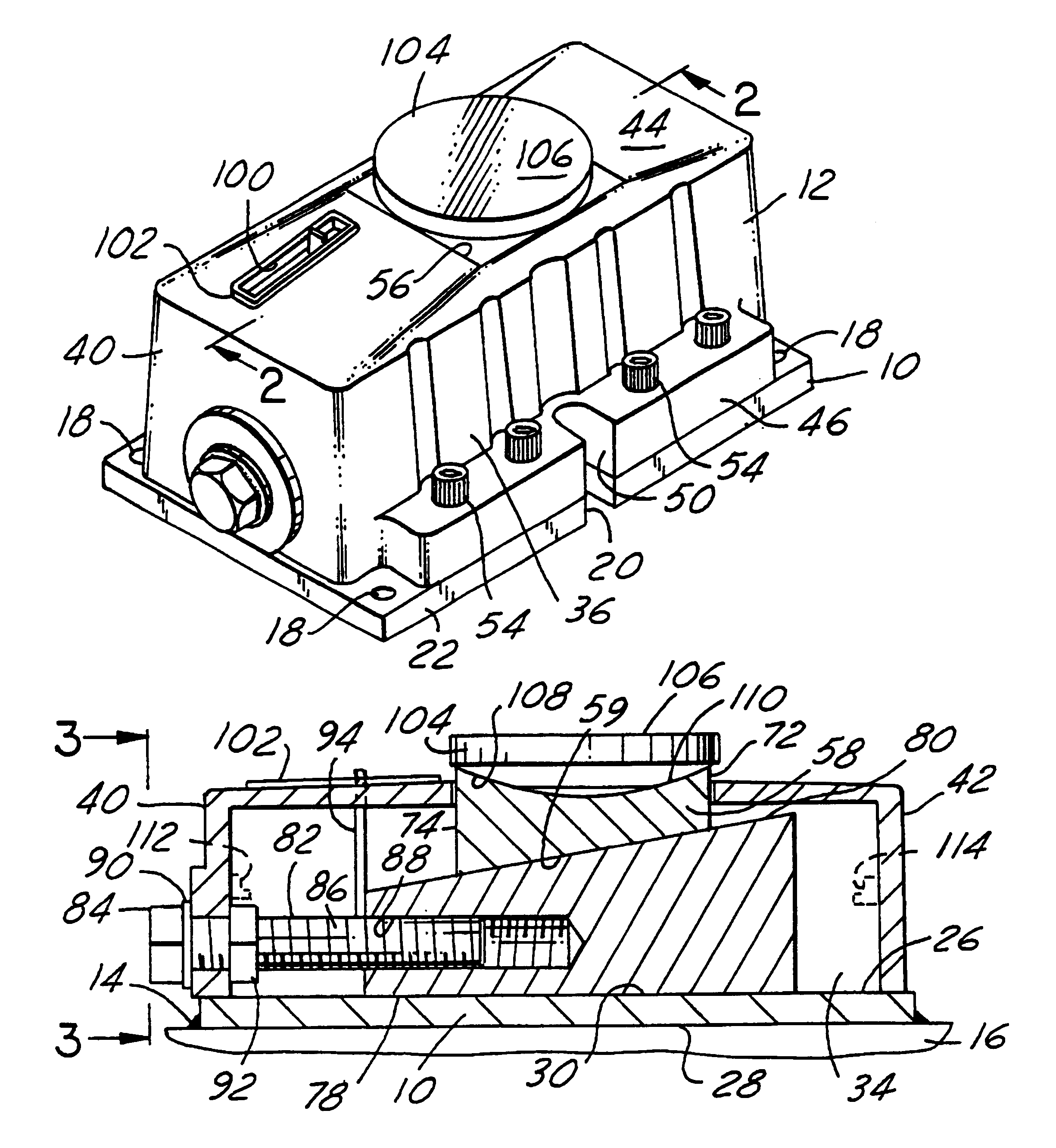
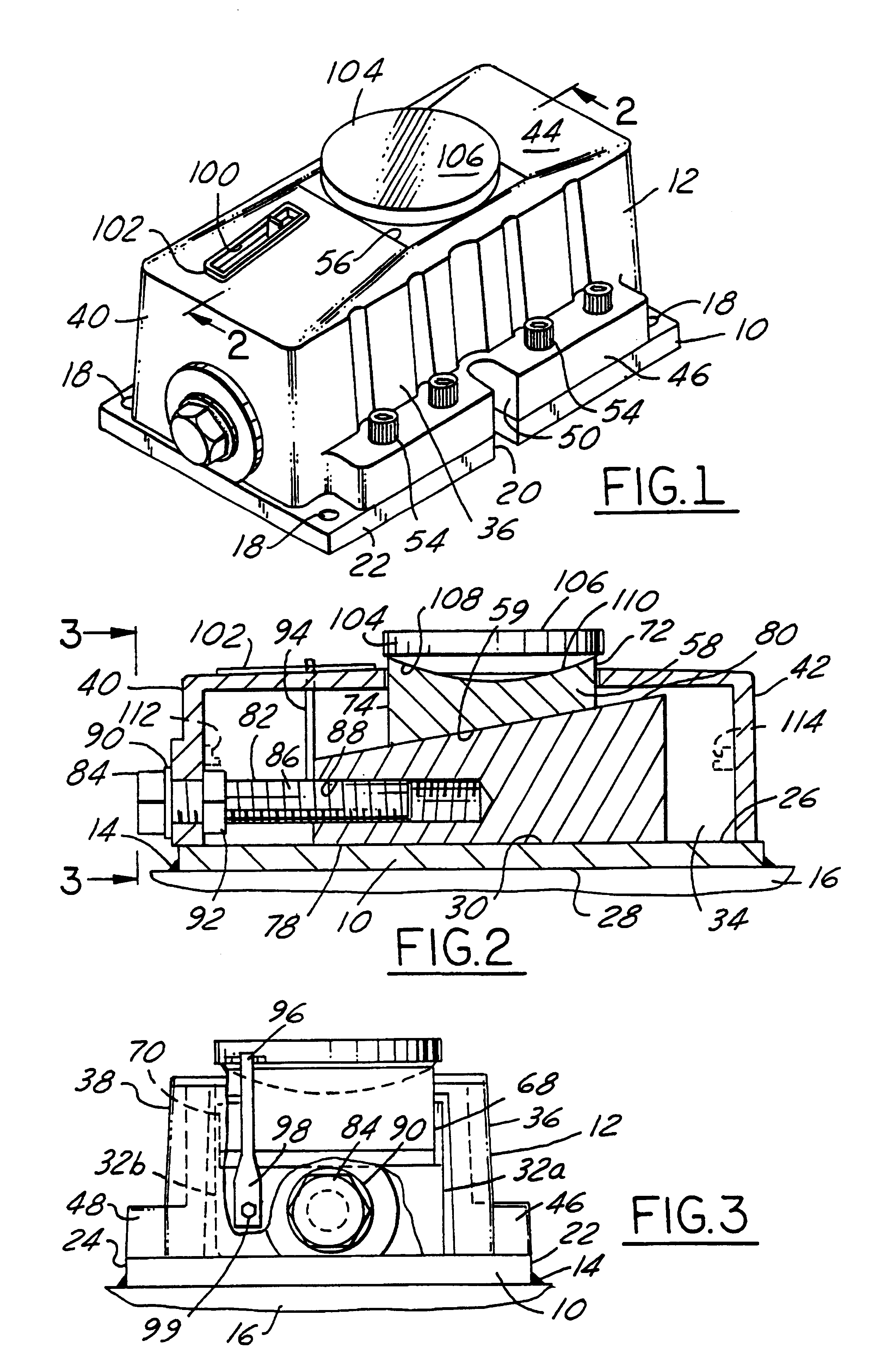
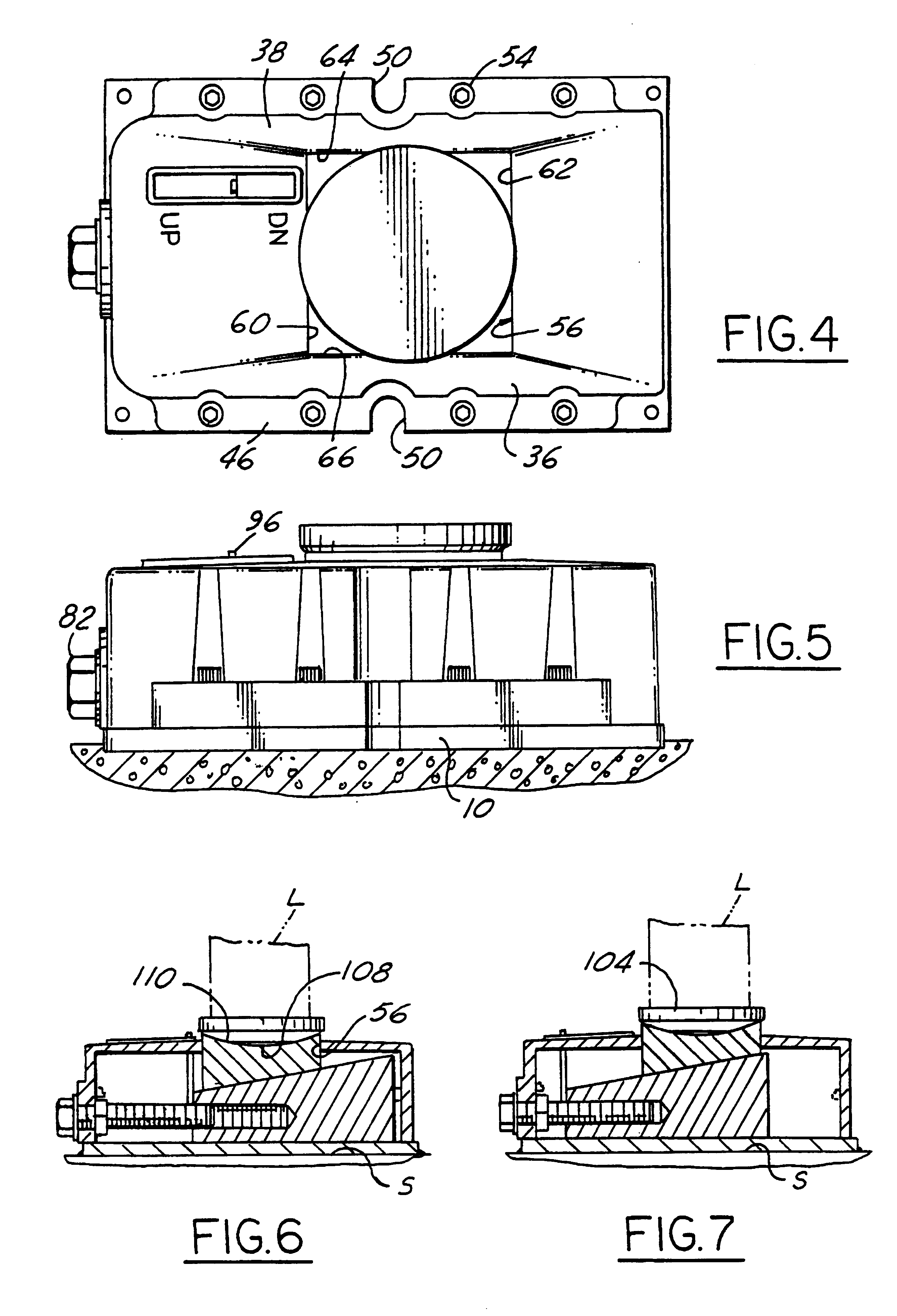
The leveler, as shown in the drawings, has a steel base plate 10 which may be of any desired size to carry the load. It is shown in the drawings as being just large enough to accommodate the cover 12, and while it should be no smaller, it can be substantially larger. The leveler design permits a customer to order the leveler with either a standard base, such as shown in FIG. 1, or any larger size base desired. Because the base is made of steel, it can be welded, as at 14, to a structural part 16 of the building in which the leveler is installed, or it can be installed with concrete anchors or other fasteners (not shown) as in the prior art. Threaded holes 18 at each of the corners of the plate, are provided for threadedly receiving therethrough levelling screws to level the base prior to grouting it in place in the concrete floor. Slots 20, one in each edge 22 and 24 are adapted to permit fasteners to be attached to the leveler to hold it down to the structure of the building. Prior...


PUM


Abstract

A leveling device for heavy loads having a weldable base (10) and a cast iron cover (12) secured thereto with a wedge (32) disposed within the cover (12) and slidably supported on the base (10), a wedge follower (58) resting on the wedge (32) and extending through the cover (12), a spherical washer (106) seated at an upper end of the wedge follower (58), an adjusting screw (82) for adjusting the position of the wedge (32) within the cover (12), and a wedge position indicator (96) extending upwardly through the cover (12) to show the position of the wedge (32) therewithin.

Description

This invention relates to leveling devices and particularly to such devices for mounting and leveling heavy loads.Background of the InventionMachine levelers in various forms have been sold over the years whose designs are represented by the following U.S. Pat. Nos. 1,987,726 4,114,845 2,819,037 4,576,357 3,306,562 4,858,865 3,325,145 5,110,082Certain improvements, however, are desirable, such as, for example, being able to weld the leveling device to steel beams in the floor of the building. Heretofore the leveling devices have had cast iron bases or housings which do not lend themselves to welding and had to be secured to the floor by screws as in U.S. Pat. Nos. 1,987,726, 3,325,145 or 5,110,082, or simply grouted in place in the floor. Also, the design of the prior art levelers was such that if a customer wanted other than a standard size base, it was difficult to provide another size base without a substantially greater price. In addition, it is desirable that the leveler it be ...

Claims


Application Information

Patent Timeline
IPC IPC(8): F16M7/00
CPCF16M7/00
Inventor SCHRIEVER, FREDERICK G.
Owner SCHRIEVER FREDERICK G
Why Eureka
Eureka Blog
Learn More