Horizontal electric connector

a horizontal and electric connector technology, applied in the direction of coupling device connection, coupling base/case, securing/insulating coupling contact member, etc., can solve the problems of increasing the possibility of defective connection and short circuit, losing coplanarity, and leg tending to be deformed

Inactive Publication Date: 2004-03-09
JST MFG CO LTD
View PDF18 Cites 11 Cited by
  • Summary
  • Abstract
  • Description
  • Claims
  • Application Information

AI Technical Summary

Benefits of technology

When this horizontal electric connector is placed in such a way that its bottom faces a printed circuit board or the like, and the connecting parts at the top ends of the legs of the first electric contact and the second electric contact are soldered onto the printed circuit board or the like, the horizontal electric connector will be mounted onto the printed circuit board or the like. In this case, as the leg of the second electric contact extends forwards along the bottom, even if the horizontal electric connector is subjected to a force in the front-rear direction, the forces to which the connecting parts will be subjected will be reduced, and moreover, troubles, such as short circuit caused by a solder waste or the like caught between the connecting parts will be prevented. Furthermore, as the leg of the second electric contact is press-fitted into the leg supporting part on the bottom of the insulating housing from the rear, the leg will hardly undergo deformation in the height direction and the width direction. As a result, the coplanarity of the second electric contacts will be obtained reliably and defective connection and short circuit will be prevented.
Accordingly, the horizontal electric connector according to the present invention can reduce the force to which the connecting parts are subjected when the connector is subjected to a force in the front-rear direction because the leg of the second electric contact extends along the bottom of the connector. Moreover, the horizontal electric connector of the present invention can prevent occurrence of troubles such as a short circuit between connecting parts due to a solder waste, etc. As the leg of the second electric contact is supported on the bottom of the insulating housing, the leg hardly undergoes deformation in the height direction and the width direction, and the coplanarity of the second electric contacts can be obtained stably, and defective connection and short circuit can be prevented reliably.

Problems solved by technology

Because of this, the leg tends to be deformed due to external forces.
If the leg is deformed, the bottom of the leg and the bottoms of legs of other second electric contacts will become irregular to each other, losing the coplanarity, or increasing the possibility of defective connection and short circuit.

Method used


Image

  • Horizontal electric connector
  • Horizontal electric connector
  • Horizontal electric connector

Examples


Embodiment Construction

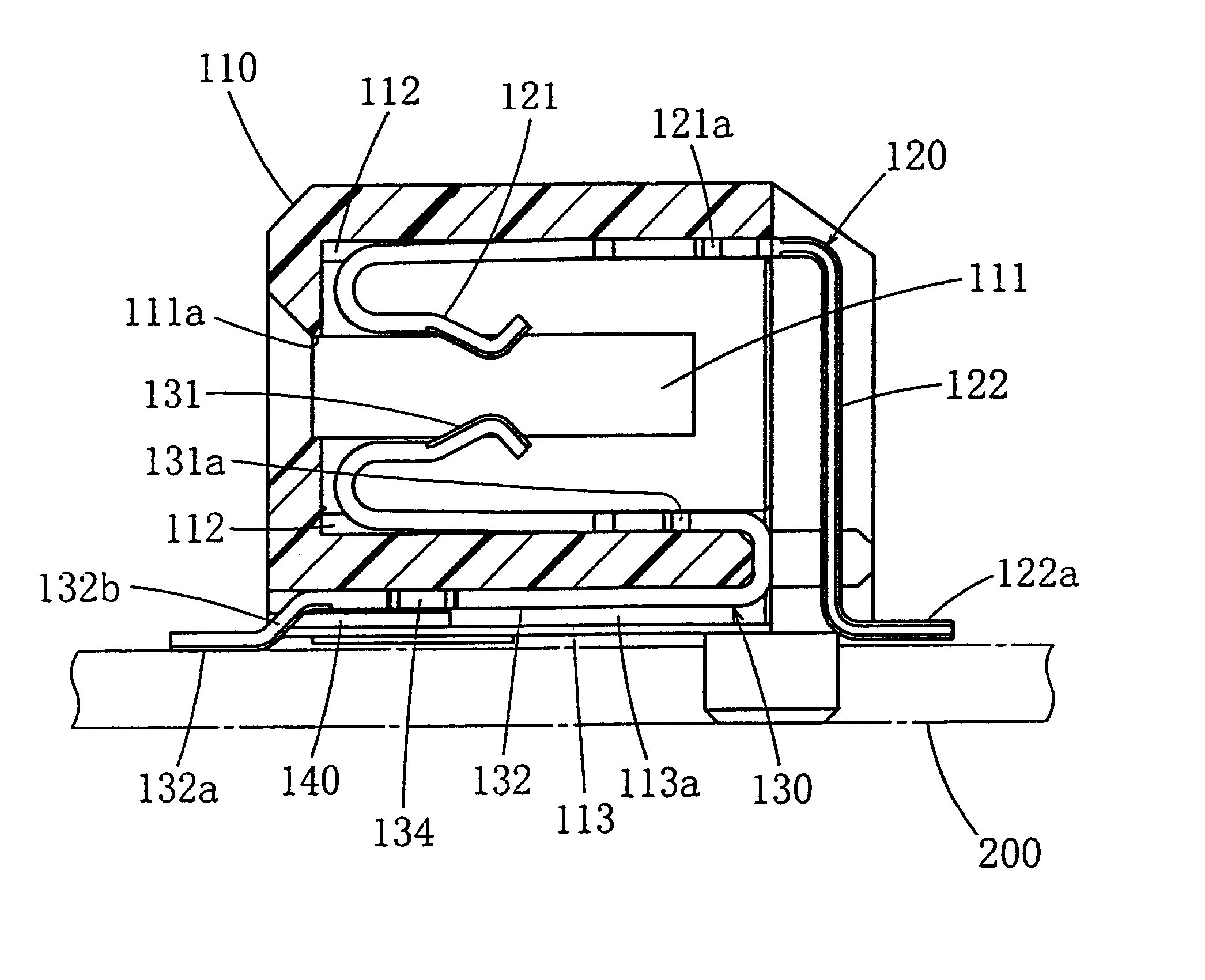
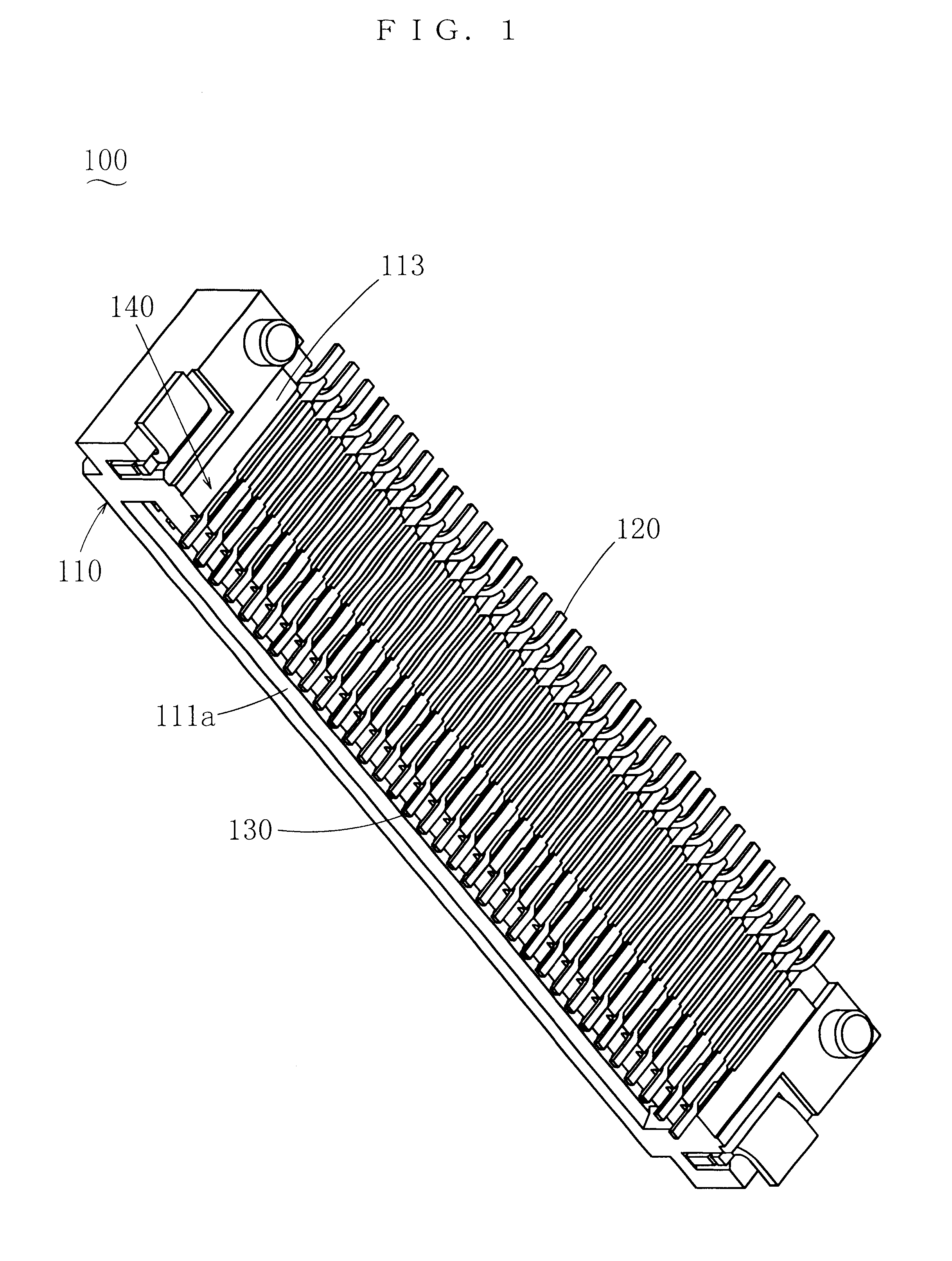
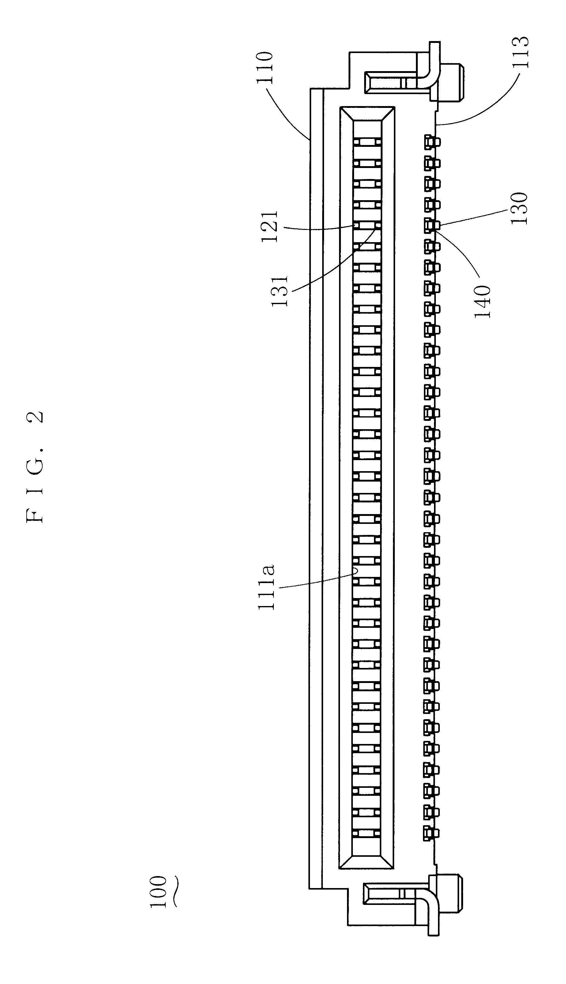
In the following, some embodiments of the present invention will be described. FIG. 1 through FIG. 4 show a horizontal electric connector 100 being the embodiment. This electric connector 100 is a card-edge connector which is to be horizontally mounted on a printed circuit board 200, and the top end of an IC card or the like will be inserted, in a direction almost in parallel with the printed circuit board 200, into the electric connector 100 through an insertion port that opens in one end of the electric connector 100.

In FIG. 1 through FIG. 4, 110 denotes an insulation housing that is formed of an insulating material such as resin. A chamber 111 is formed in this insulating housing 110. The chamber 111 is open rearwards. A receiving port 111a for receiving an IC card or the like, which is through to the chamber 111, is formed at the front of the insulating housing 110. A first electric contact 120 and a second electric contact 130 are press-fitted into the insulating housing 110 fr...


PUM


Abstract

A horizontal electric connector includes an insulating housing, a first electric contact, with a contacting part that is press-fitted into the housing from the rear and contacts a counterpart conductive part, and a leg that extends from the contacting part, comes out of the housing at the rear and descends, and a second electric contact, with a contacting part that is press-fitted into the housing from the rear at a position lower than the first electric contact and contacts a counterpart conductive part, and a leg that extends from the contacting part, comes out of the housing at the rear and extends forward along the bottom of the housing. A leg supporting part is provided on the bottom of the housing, into which the leg of the second electric contact is press-fitted from the rear, to prevent deformation of the leg.

Description

1. Field of the InventionThe present invention belongs to a field of electric connectors that are horizontally mounted on a printed circuit board, etc., and relates to a structure for supporting electric contacts on an insulating housing.2. Related ArtA horizontal electric connector is known as one of the above-mentioned horizontal electric connectors. This horizontal electric connector comprises an insulating housing, a first electric contact, which has a contacting part that is fixed on the insulating housing and contacts a counterpart contact, and a leg that extends from the contacting part, comes out of the insulating housing at the rear thereof and descends, and a second electric contact, which has a contacting part that is fixed on the insulating housing at a position lower than that of the first electric contact and contacts a counterpart contact, and a leg that extends from the contacting part, comes out of the insulating housing at the rear thereof and extends forwards alon...

Claims


Application Information

Patent Timeline
Patent Type & Authority Patents(United States)
IPC IPC(8): H01R13/41H01R13/40H01R12/55H01R12/71H01R13/46
CPCH01R12/716H01R13/41H01R12/721H01R13/46
Inventor KURODA, KEIJIMIYAMOTO, DAICHI
Owner JST MFG CO LTD
Why Eureka
Try Eureka