Rangefinder

a rangefinder and sensor technology, applied in the field of rangefinders, can solve the problems of destroying the detector or at the very least saturating the sensor, saturating the sensor, and/or distorting the range computation of the rangefinder

Inactive Publication Date: 2006-08-03
STATE OF ISRAEL MINIST OF AGRI & RURAL DEV AGRI RES ORG (A R O) (VOLCANI CENT)
View PDF5 Cites 7 Cited by
  • Summary
  • Abstract
  • Description
  • Claims
  • Application Information

AI Technical Summary

Benefits of technology

[0014] In accordance with an additional feature of the present invention, the controller is further configured for shorting a connection within the second detector so as to render the second detector insensitive to the reflections of the pulses from less than a minimum range.

Problems solved by technology

These reflections can destroy the detector or at the very least saturate the sensor.
Additionally, back-scattering from atmospheric aerosols can saturate the sensor and / or distort the range computations of the rangefinder.

Method used


Image

  • Rangefinder
  • Rangefinder
  • Rangefinder

Examples


Embodiment Construction

[0022] The present invention is a rangefinder construction and method of operation thereof.

[0023] The principles and operation of a rangefinder according to the present invention may be better understood with reference to the drawings and the accompanying description.

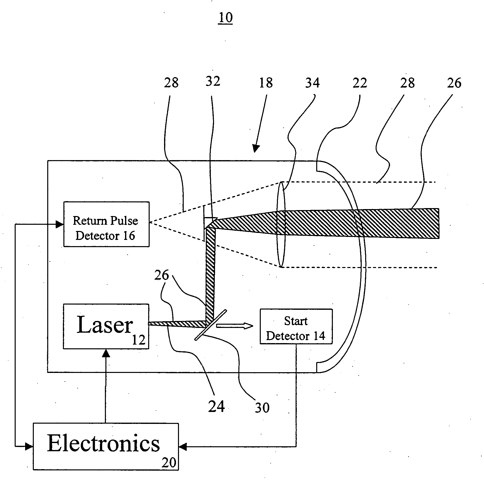
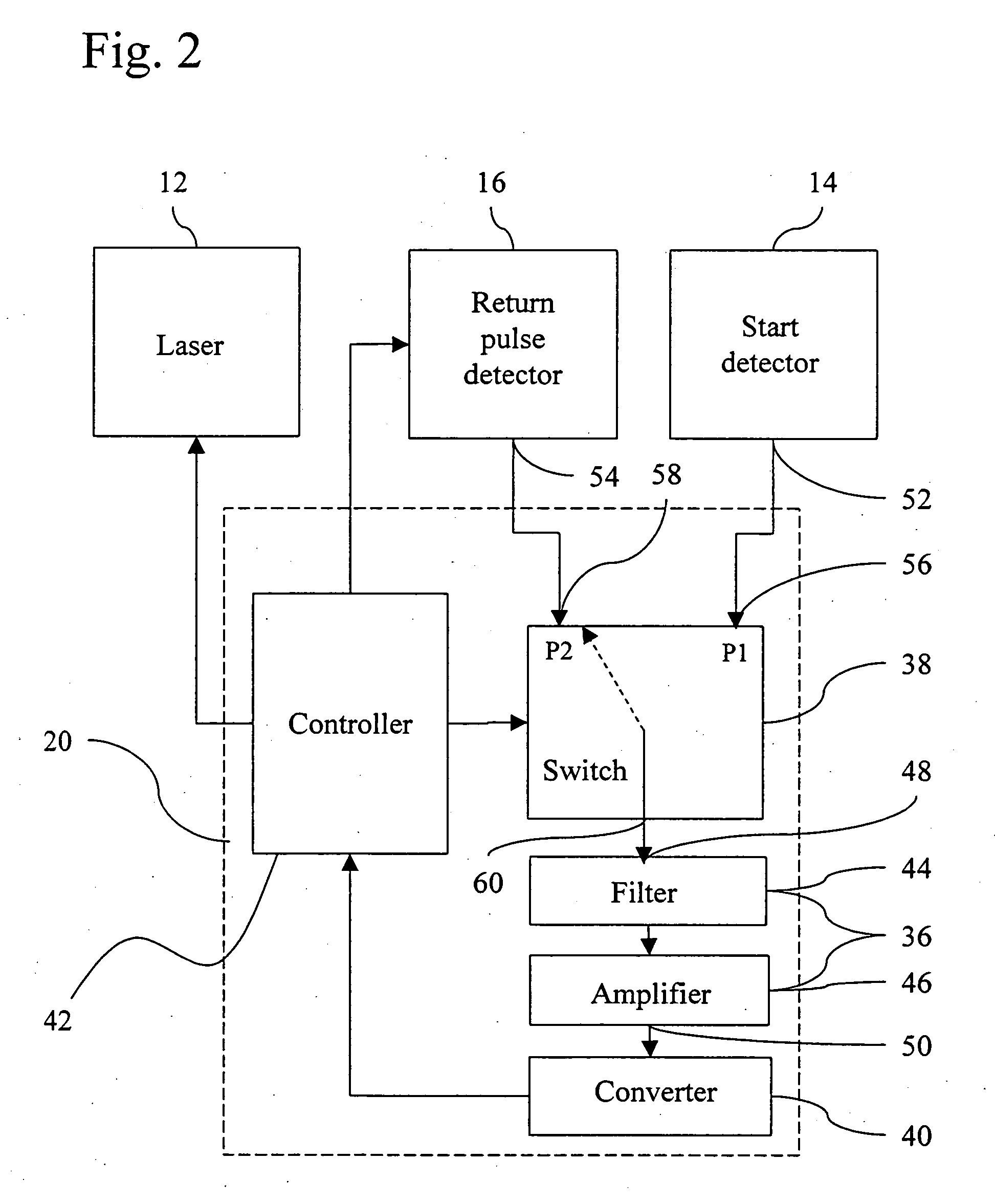
[0024] Reference is now made to FIG. 1, which is schematic view of a rangefinder system 10 for determining a range of an object (not shown) that is constructed and operable in accordance with a preferred embodiment of the invention. Rangefinder system 10 includes a source of laser radiation 12, a start detector 14, a return pulse detector 16, an optical arrangement 18, an electronic arrangement 20 and a window 22. Source of laser radiation 12 is typically configured for transmitting a plurality of pulses 24 of near-infrared laser radiation. Source of laser radiation 12 is defined herein to include a laser for producing pulses from in the range from visible light to infrared. Start detector 14 is typically a PIN photod...


PUM


Abstract

A range finder system for determining a range of an object. The system includes a source of laser radiation configured for transmitting a plurality of pulses, a first detector, a second detector, an optical arrangement configured for directing the pulses along an outgoing path and receiving the pulses reflected by the object along a return path. The first detector is deployed to be responsive to the pulses traveling along the outgoing path and the second detector insensitive to the reflections of the pulses from less that the minimum range. The system further includes a controller configured for shorting a connection within the second detector to make the second detector insensitive to the reflections of the pulses from less than a minimum range, and for determining the range of the object based upon a time-of-flight of one or more of the pulses based upon output signals of the first detector and the second detector.

Description

FIELD AND BACKGROUND OF THE INVENTION [0001] The present invention relates to rangefinders and, in particular, it concerns rangefinders for use in a guided missile. [0002] By way of introduction, rangefinders are typically installed behind a window of a missile seeker head. The window is generally formed from a heat resistant material such as sapphire. Additionally, it is advantageous for the laser and detector of the range finder to share the same optical channel in order to make the rangefinder compact. However, up to 10% of the outgoing laser pulses are reflected back by the seeker head window to the detector. These reflections can destroy the detector or at the very least saturate the sensor. [0003] Additionally, back-scattering from atmospheric aerosols can saturate the sensor and / or distort the range computations of the rangefinder. [0004] There is therefore a need for an accurate rangefinder which prevents the detector from being saturated or destroyed by reflections from the...

Claims


Application Information

Patent Timeline
Patent Type & Authority Applications(United States)
IPC IPC(8): G01C3/08G01S17/10G01S17/14
CPCG01S7/497G01S17/10G01S17/105G01S17/14
Inventor ABURMAD, SHIMONCHISHINSKI, EHUDLANGER, THOMAS
Owner STATE OF ISRAEL MINIST OF AGRI & RURAL DEV AGRI RES ORG (A R O) (VOLCANI CENT)
Why Eureka
Try Eureka